OM-257 798 Page 17
SECTION 5 − INSTALLATION
! Special installation may be
required where gasoline or
volatile liquids are present −
see NEC Article 511 or CEC
Section 20.
! Do not stack units. Beware of
tipping.
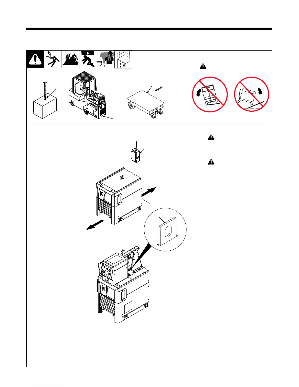
1 Lifting Eye
. When a feeder is installed on
top of power source, lift eye is
inserted through slot in feeder
base.
2 Lifting Forks
Use lifting eye or lifting forks to
move unit.
If using lifting forks, extend forks
beyond opposite side of unit.
3 Hand Cart
Use cart or similar device to move
unit.
4 Line Disconnect Device
Locate unit near correct input
power supply.
5-1. Selecting A Location
4
18 in.
(460 mm)
18 in.
(460 mm)
OR
1
2
Movement
Location And Airflow
Ref. 259 119-A
3
OR
! Do not move or operate
unit where it could tip.
Tipping
1





 To Next Page