OM-257 798 Page 21
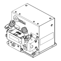
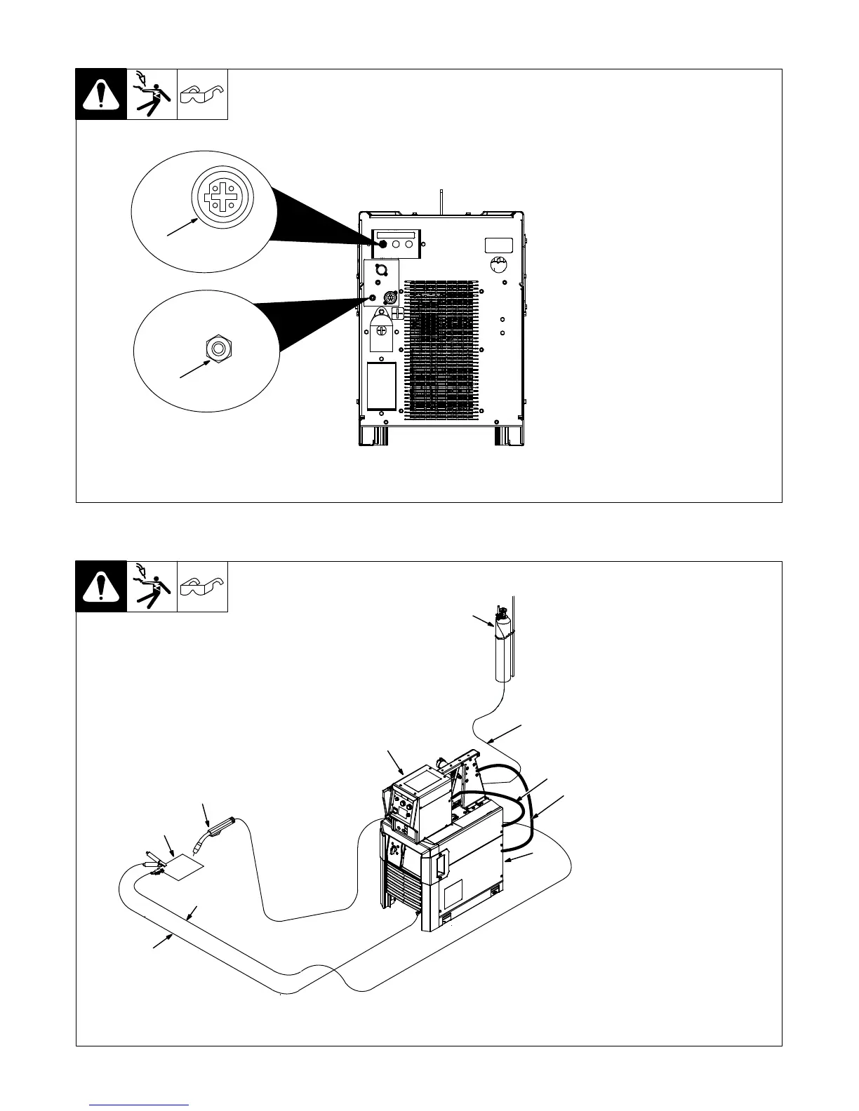
5-6. Supplementary Protector CB1 And Optional Communication Panel
1 Optional Ethernet Receptacle
Used for connecting a computer di-
rectly to the power source to ac-
cess configuration web pages.
2 Supplementory Protector CB1
CB1 protects the wirefeed motor
from overload. If CB1 opens, the
wirefeeder does not work.
. Press button to reset breaker. If
breaker continues to open,
contact a Factory Authorized
Service Agent.
Ref. 259 119-A
2
1
Ref. 269790-A
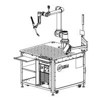
5-7. Connection Diagram
1 Welding Power Source
2 Wire Feeder
3 Gas Cylinder
4 Gas Hose
5 Feeder Cable
6 Electrode Cable
7 Work Cable
8 Volt Sense Lead
9 Welding Gun
10 Workpiece
. Shielding gas pressure not to
exceed 100 psi (689 kPa).
1
2
3
4
5
8
9
6
7
10