OM-257 798 Page 54
. Hardware is common and
not available unless listed.
269 782-A
1
2
3
4
4
4
5
5
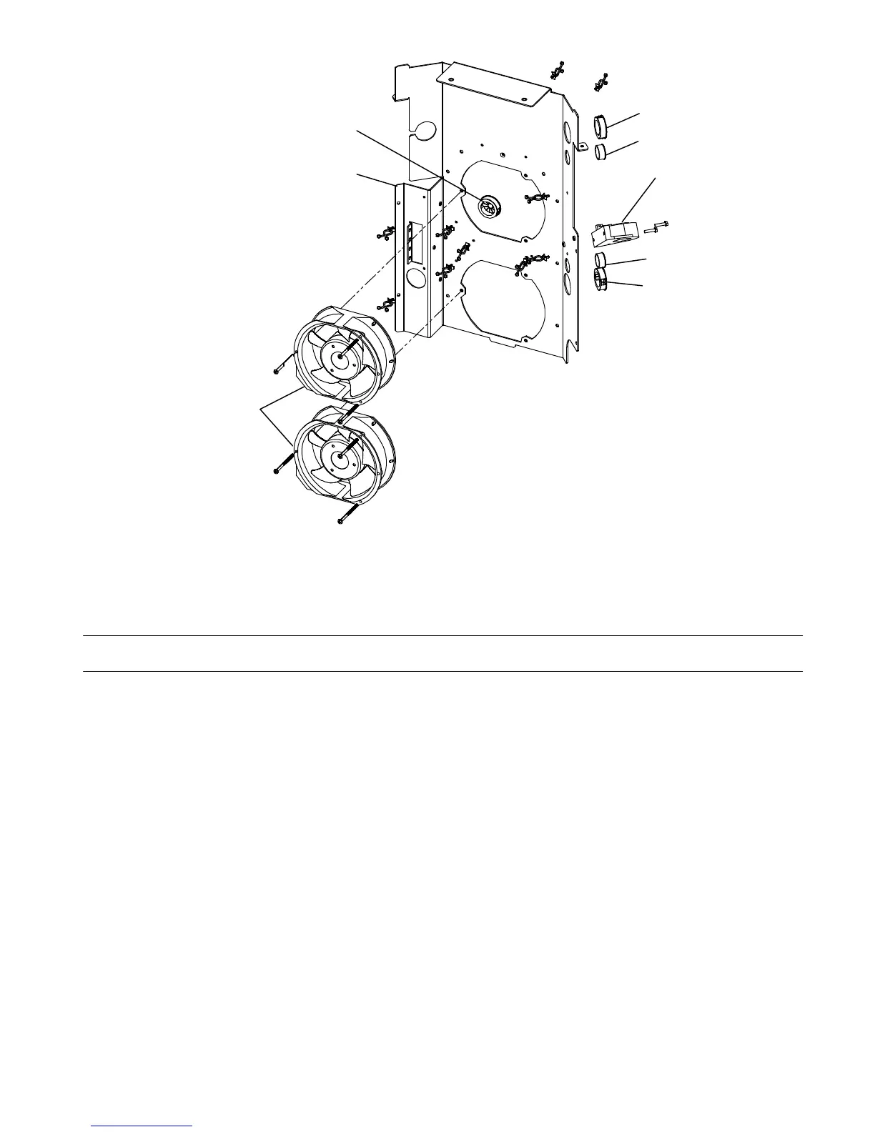
Figure 11-4. Fan Panel Assembly
Description
Part
No.
Dia.
Mkgs.
Item
No.
Figure 11-4. Fan Panel Assembly (Figure 11-1, Item 7)
Quantity
1 265241 Panel, Fan Motor 1.. .............. .. ................................................
2 FM1-FM2 213072 Fan, Muffin 115v 60hz 3400 Rpm 6.378 Mtg Holes 2.. .. .. .. ..................
3 HD1 168829 Transducer, Current 1000a Module Max Open Loop 1.. .... .... .. .................
4 245520 Bushing, Snap-in Nyl 1.062 Id X 1.500 Mtg Hole Cent 3.. .............. .. ................
5 153403 Bushing, Snap-in Nyl .750 Id X 1.000 Mtg Hole Cent 2.. .............. .. .................
+ When ordering a component originally displaying a precautionary label, the label should also be ordered.
To maintain the factory original performance of your equipment, use only Manufacturer’s Suggested
Replacement Parts. Model and serial number required when ordering parts from your local distributor.