OM-261050 Page 21
SECTION 5 − INSTALLATION
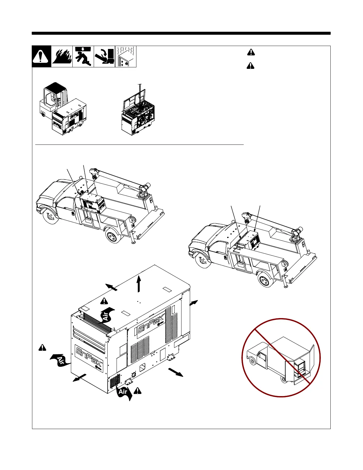
! Do not move or operate unit
where it could tip.
! Always securely fasten unit
onto transport vehicle and
comply with all DOT and other
applicable codes.
Go to MillerWelds.com for more
information on truck installations.
NOTICE − Do not install unit where
air flow is restricted or engine may
overheat.
See Section 5-2 for mounting in-
formation. See Section 4-7 for di-
mensions.
See Section6 through 9 for spe-
cific EnPak systems information.
1 Hydraulic Reservoir
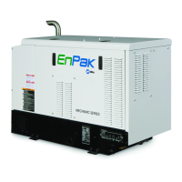
2 EnPak
Typical hydraulic reservoir place-
ment in relation to EnPak. See Sec-
tion 7-1 for complete reservoir re-
quirements.
Ref: install3 2014−12 − 805 454-A / 265 802-A
Movement
5-1. Installing Unit
OR
Location/Airflow Clearance
1 in.
(25 mm)
7 in. (178 mm) Maintenance
4 in. (102 mm) Operation
18 in.
(460 mm)
1 in.
(25 mm)
1
2
1
2
7 in. (178 mm) Maintenance
4 in. (102 mm) Operation
! Hot air.
! Hot air.
! Hot air.




 To Next Page