OM-261050 Page 39
SECTION 9 − AUXILIARY POWER SYSTEM CONNECTIONS
! Always ground auxiliary power
system to vehicle frame to pre-
vent electric shock and static
electricity hazards.
! Also see AWS Safety & Health
Fact Sheet No. 29, Grounding of
Portable And Vehicle Mounted
Welding Generators.
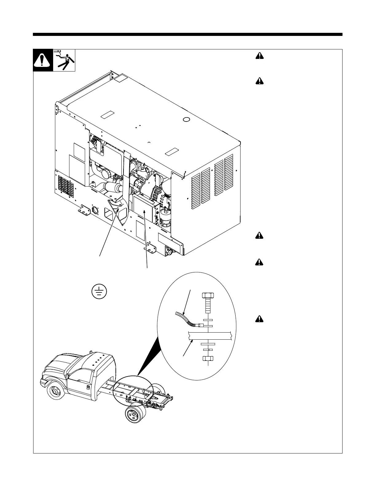
1 Auxiliary Power System Ground
2 Grounding Cable (Not Supplied)
3 Metal Vehicle Frame
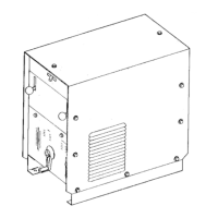
4 Auxiliary Power Box
Connect grounding cable to auxiliary
power system ground (ground screw
on frame where existing green or
green/yellow lead is attached).
Route grounding cable through auxili-
ary power box and through ground wire
route hole, away from hot, sharp or
moving parts.
Route grounding cable to appropriate
termination point on metal vehicle
frame. Use #8 AWG or larger insulated
copper wire with green or green striped
insulation.
Electrically bond generator frame
to vehicle frame by metal-to-metal
contact.
! Always connect a ground wire
from the auxiliary power system
ground to bare metal on the ve-
hicle frame as shown.
! Use only Miller-recommended
GFCI receptacles (see Parts
List). The generator does not
provide usable power at engine
idle speed (1800 rpm). Other
GFCI receptacles cannot be
used. The low frequency/low
voltage may prevent other GFCI
receptacles from operating
properly.
! Test GFCI receptacles at least
once a month by running engine
at high speed and pressing Test
button to verify GFCI recept-
acles are working properly.
-1. Grounding Auxiliary Power System To Truck Frame
265 802-A / 805 447-A / Ref 287 066
3
2
4
Existing Green or
Green/Striped Lead
1
GND/PE




 To Next Page