– 1.4 –
1-4. Names of parts
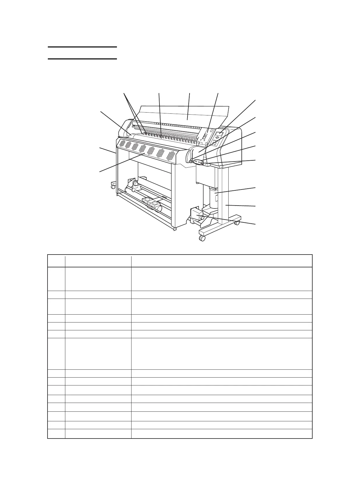
1-4-1. Front face
Name Function
1 Front cover It is opened when setting medium or taking a corrective measure against
a medium jam. Even if the power switch is off, keep the front cover
closed to perform the ink clogging preventive operation.
2 Carriage Moves the print head from side to side.
3 Operation panel This panel has the operation keys required for operating the device and
the LCD for displaying set items, etc.
4 Capping station Incorporates the ink cap to be capped on the head and the wiper, etc.
5 Clamp lever It is made to go up-down the pinch roller for holding medium.
6 Heater operation panel Provides the heater power switch and the heater status LED indicator.
7 Power switch It turns on/off the power to the device.When the power switch is turned
on, the POWER indicator lights in green. While the main power switch is
on, the ink clogging preventive operation (Flashing) is performed
periodically even if the power switch is off.
8Waste ink tank Waste ink gathers in this tank.
9 Stand It supports the main unit. It is provided with casters to move the device.
10 Take-up device It supports to wind up the roll medium printed.
11 Drier fan unit * Dries plotted ink.
12 Front exhauster * Discharges plotting smell from the media to out of the room.
13 Maintenance cover It is opened during maintenace work.
14 Platen Paper is ejected along the platen. Two heaters are built in.
15 Printer heater Fixes and dries printing ink. ( Attached inside the platen )
1
2
3
4
5
6
7
8
9
10
11*
12*
13
14
* Option for JV3-75SPII
15
 Loading...