Do you have a question about the MIMAKI JV3-160SP and is the answer not in the manual?
Important safety precautions and warnings for performing maintenance work on the plotter.
Guidance on effectively using the maintenance manual to diagnose and resolve issues.
Lists essential tools and measuring apparatus necessary for performing maintenance tasks.
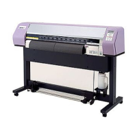
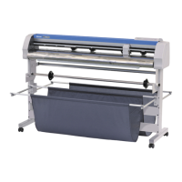
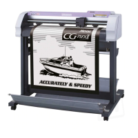
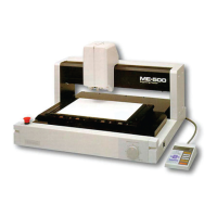
Identification of key components and parts of the plotter.
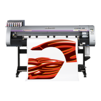
Technical specifications and operational parameters of the plotter models.
Detailed explanation of the plotter's various electrical components and their functions.
Defines key terms related to the ink system, such as Ink system, Head capping, and Clogged nozzle.
Explanation of the media size detection process and a flowchart of media width detection.
General procedures for recovering from troubles indicated by LCD error messages.
List of error messages with numbers displayed on the LCD, their causes, and corrective actions.
Troubleshooting steps for issues that do not trigger specific error messages on the LCD.
Diagnosing and fixing causes of unclear or missing lines and displaced characters in prints.
Addressing issues with incorrect indications of remaining ink levels and potential inaccuracies.
Flowchart for maintenance procedures following the replacement of key plotter parts.
Key maintenance procedures and adjustments for plotter components.
Procedure for replacing the S-Print head assembly, including disassembly and reassembly steps.
Guide for adjusting the head angle to ensure proper print alignment and quality.
Detailed instructions for replacing the print heater or preheater, including parts and tools.
Overview of functions available in maintenance mode, including #ADJUST, #TEST, and #PARAMETER items.
Methods for entering the maintenance mode via plotter actuation or system parameters.
Detailed list and procedures for various adjustment functions within the #ADJUST menu.
List and procedures for diagnostic tests within the #TEST menu to check machine status.
Description of parameter items, including SYSTEM PARAMETER and its configuration.
Procedures for transferring parameters between the plotter and a host computer.
Instructions for updating the plotter's firmware via IEEE1394 or IEEE1284 interface.
Hierarchical diagram illustrating the structure and options within the maintenance mode menus.
First part of a block diagram showing the electrical components and their interconnections.
Second part of a block diagram illustrating the heater system components and wiring.
| Maximum Print Width | 1600 mm |
|---|---|
| Power Requirements | AC 100-240V, 50/60Hz |
| Technology | Solvent |
| Printing Method | Piezoelectric |
| Print Resolution | 1440 x 1440 dpi |
| Ink Type | Solvent ink |
| Ink Colors | CMYK |
| Media Types | banner |
| Media Thickness | Up to 1 mm |
| Interface | USB |