– 4.24 –
4-2-10. Adjustment of the Linear sensor PCB assy height
[The case that needs adjustment]
• In the case where the Linear sensor PCB assy has been replaced.
• In the case where the Linear encoder scale has been replaced.
[Tools to be used]
• Phillips screwdriver
(No.2 for M3 to M5)
[Adjusting procedure]
1) Loosen the screws in the Linear
sensor PCB assy on the slider.
2) Within the movable range of the
slider, move the assy up and down
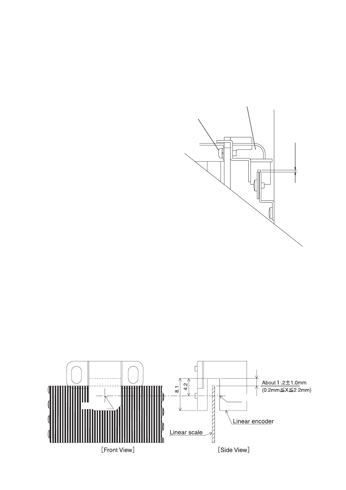
so that the gap between the linear
encoder scale and linear sensor PCB
is about 1.2 mm ± 1.0 mm.
Mounting screw
Linear sensor PCB assy.
< Mounting position of the linear encoder PCB >
Attach the linear encoder PCB assy so that the mounting position (overlapping condition
to the linear scale) satisfies the following rough standard over the entire scale. Also check
1) and 2) below.
1) The following overlapping condition is met at the right, center, and left of the device.
2) The linear scale is positioned approximately at the center of the sensor's recessed section
but does not contact the wall.
Optical axis
Optical axis
1.2 mm ± 1.0 mm
 Loading...