© 2009 MIMAKI ENGINEERING CO.,LTD.
3.2.3 P.1
1
2
3
4
5
6
7
8
R.1.1
Maintenance Manual > Workflow > Cut Head Carriage > Replacement of the Mark Assy
Model CJV30/TPC Issued 2008.08.04 Revised 2008.09.17 F/W ver. 1.20 Remark
1.1
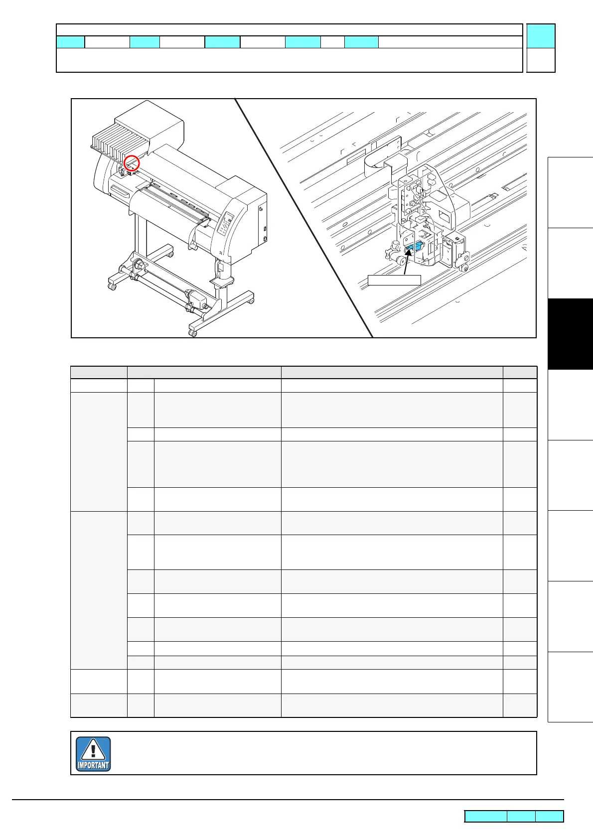
3.2.3 Replacement of the Mark Assy
List of replacement procedures
Item Work operation Description Ref.
Covers
1.
Removal of covers, etc. Remove the C head cover and CY cover F. 6.1.1
Mark Assy
2.
Removal of the auto cutter assy
and pen assy.
Be sure not to change the direction of the hook of the baffle
SP. If its direction is changed, the pen pressure and landing
are also changed.
6.3.1
3.
Removal of the mark assy. Remove the mark assy. 6.3.3
4.
Mounting of the mark assy. Mount the mark assy.
Set the pressure of all the clamps to Middle, and clamp the
assy. Then adjust so that the assy is positioned 2.5 mm above
the platen on the right station side.
6.3.3
5.
Mounting of the pen assy and
auto cutter assy.
Mount the auto cutter assy. 6.3.1
Adjustment
6.
Adjustment of the pen stroke. Adjust so that the pen stroke is 3 ±0.3 mm as measured from
the pen point.
7.
Adjustment of the mounting
location of the cutter.
Hold down the clamp lever and adjust the mounting location
so that the distance between the auto cutter assy and the
platen is set at 8.8 mm.
4.3.2
8.
Adjustment of the sensitivity of
the photo sensor
Adjust the [#PHOTO SENS./ LV.] in [#ADJUST]. 4.2.11
9.
Adjustment of the position of the
photo sensor
Adjust the position of the photo sensor in [#ADJUST]. 4.2.12
10.
Adjustment of pen pressure and
pen landing
Adjust the [PEN PRESSURE] and [LANDING]. 4.2.9
4.2.10
11.
Pointer offset
12.
Print / Cut
Check
13.
Check each performance Check the [CUT PATTERN] and cutting position. Carry out
“print & cut” online to confirm no misalignment is found.
Covers
14.
Mounting of the covers Mount the covers that have been removed.
In installation, pay attention to harness treatment.
6.1.1
Once the S guide is removed, reinstall it while pushing the solenoid outward.
 Loading...


