E5E4
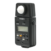
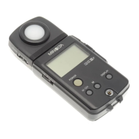
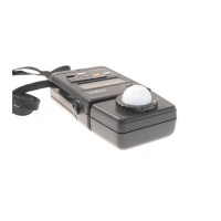
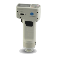
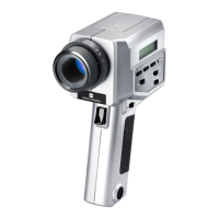
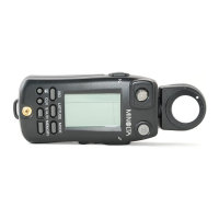
Names of Parts and Displays
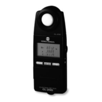
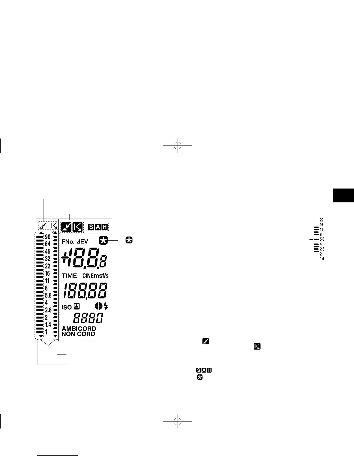
Data panel displays
Names of Parts and Displays
1. Analog scale status indicator
The left (L) and right (R) analog scales are used for incident light
measurement and spot measurement, respectively.
2. Analog scale L
The display of the pointers corresponds to measurement data and
memory data for incident light measurement. It also corresponds to the
standard exposure or latitude for incident light
measurement or spot measurement.
The small digit to the right of the two-digit
reading (f-number) on the digital readout
indicates a fractional value between stops. The
value shown on the analog display is rounded
down or up to the nearest 0.5 stops. (Values of
0.2 or lower are rounded down to 0; those of
0.3 to 0.7 are rounded to 0.5; and those of 0.8
or greater are rounded up to 1.)
When a latitude range is indicated, all dots between the upper and lower
limits are lit.
3. Analog scale R
The display of the pointers corresponds to measurement data and
memory data for spot measurement.
The small digit to the right of the two-digit reading (f-number) on the
digital readout indicates a fractional value between stops. The value
shown on the analog display is rounded down or up to the nearest 0.5
stops. (Values of 0.2 or lower are rounded down to 0; those of 0.3 to 0.7
are rounded to 0.5; and those of 0.8 or greater are rounded up to 1.)
4. Measurement data status indicator
When a value measured with incident light measurement is displayed,
the indicator appears. When a value measured with spot
measurement is displayed, the indicator appears.
5. S/A/H indicator
Holding down the S/A/H button while a measured value is displayed
lights the S, A or H indicator corresponding to the currently selected
mode.
6. indicator
This indicator turns on when the LATITUDE button is pressed.
For the purpose of explanation, the diagram above shows
all indicators that light up on the LCD.
Upper limit
1. Analog scale status
indicator
4. Measurement data status indicator
5. S/A/H indicator
6. indicator
3. Analog scale R
2. Analog scale L
Pointers
Standard
value
Lower limit
flashmetervieng.qx3302.12.259:21PMページ4