•
•
•
•
•
•
Electrical
MiR / UR Interface Operating Guide 11/2018 v.2.0 5
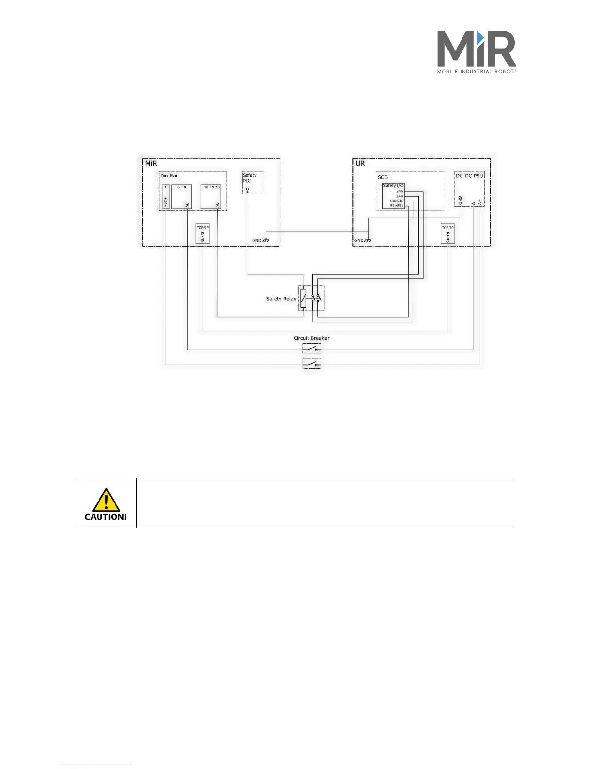
3.2 Wiring diagram
The complete electrical wiring diagram is presented first, and then it is divided to individual
Power, Safety and Communication subsections
Figure 3.1. Complete wiring diagram.
3.2.1 Power
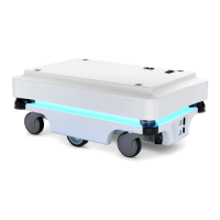
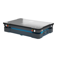
MiR100/MiR200 outputs a maximum of 24V DC - 20A continuously. The UR Robot arm and
other accessories can be connected directly to MiR100/MiR200’s power system.
Do not run a program that requires more power than the batteries can supply.
For more information regarding the UR power consumption, refer to the UR battery installation guide.




 To Next Page