MAINTENANCE
4-10
Mirage 22000/4000/6000User’s Manual
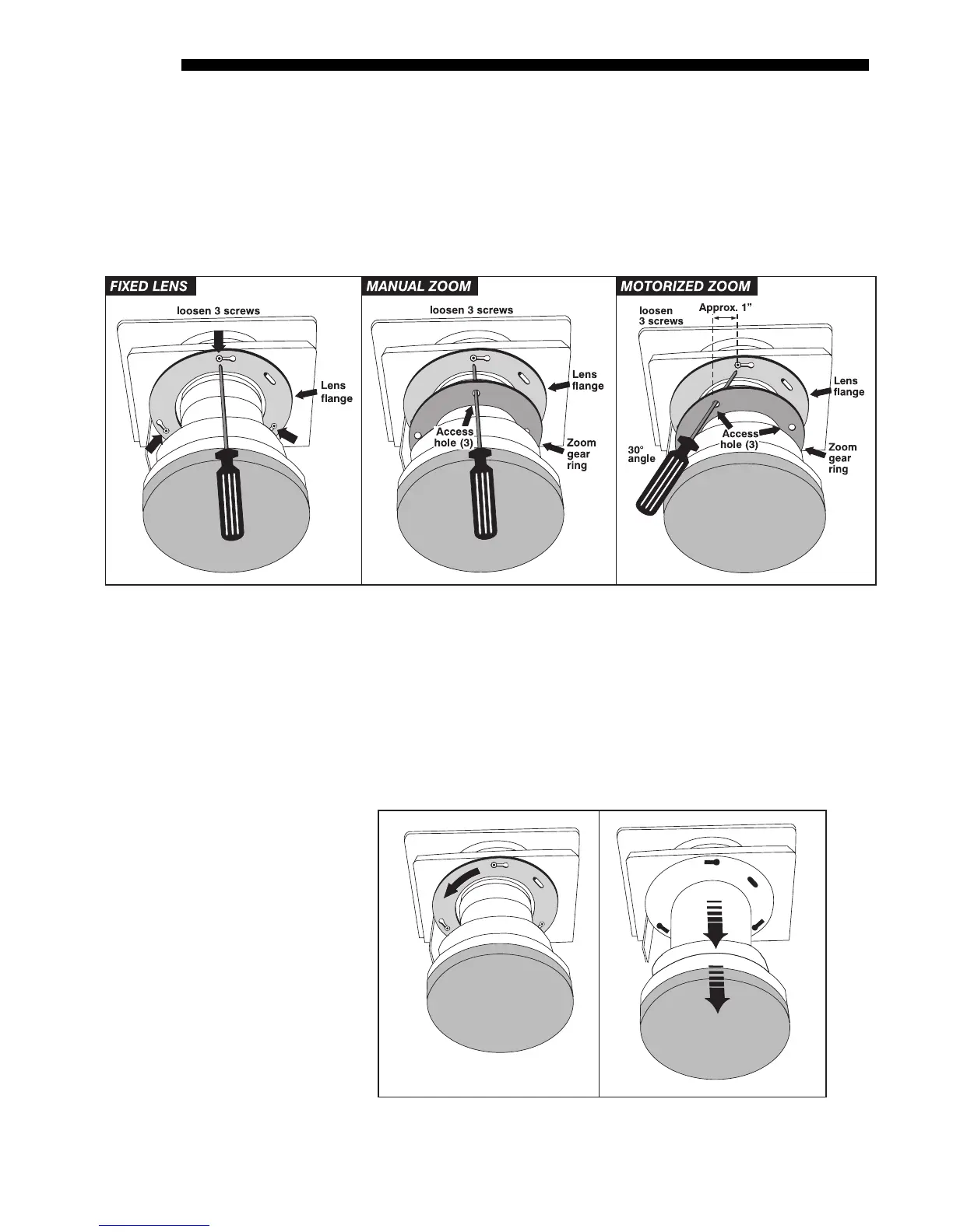
align with the screws beyond, then insert the hex socket ball driver as shown.
See Figure 4.11.
•
IF MOTORIZED ZOOM LENS:
As shown in Figure 4.11, the 3 access holes on
the zoom gear will be “skewed” away from the lens mount screws (see Before
You Begin instructions). Insert the hex socket ball driver through the holes at
approximately 30° to access each screw. Aim down for 4 o’clock screw, aim
up for 8 o’clock screw.
Figure 4.11. Accessing the Lens Mount Screws
Rotate Lens and Remove (Figure 4.12)
1. ROTATE THE LENS SLIGHTLY: See below. Using both hands, rotate the lens
barrel counterclockwise until the screw heads align with the larger end of their
slots on the lens flange.
2. PULL LENS OUT: Carefully pull the lens assembly straight out of the projector
and set aside.
Figure 4.12. Rotate Lens and Remove
(FIXED LENS SHOWN)
STEP 3
'