INSTALLATION & SETUP
Mirage 2000/4000/6000 User’s Manual
2-13
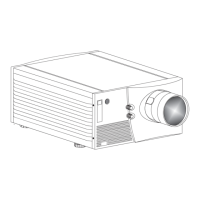
In rear screen applications where space behind
the projector is limited, a mirror may be used
to fold the optical path. See right. The position
of the projector and mirror must be accurately
set—if considering this type of installation, call
your dealer for assistance.
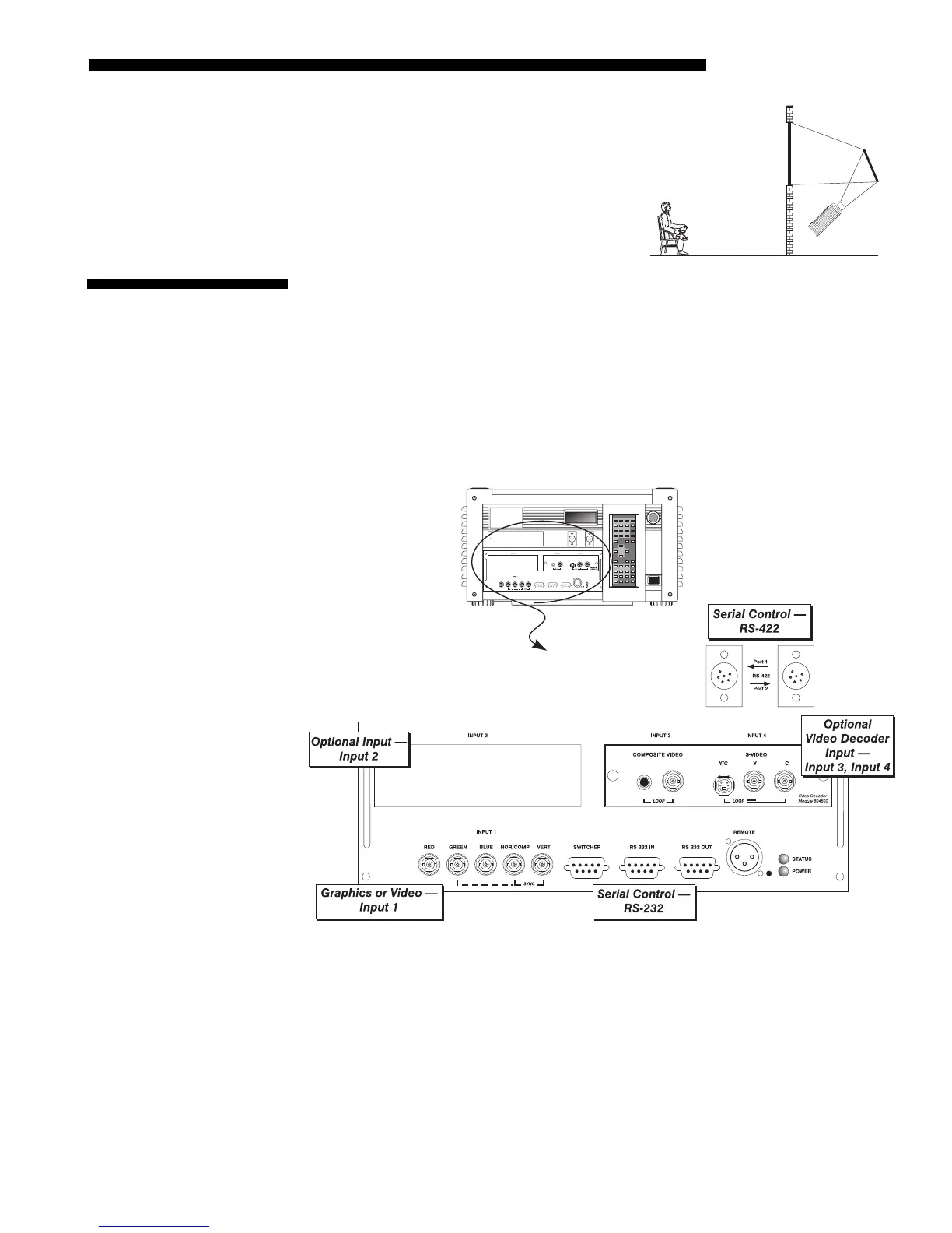
The rear panel of the projector provides standard input panels to which you may
connect a variety of sources. See Figure 2.12–the lower left area (
INPUT 1) typically
accepts an RGB signal from an external RGB source, or it can also be used for YPbPr
signals or additional video sources. The upper right panel–the optional Video
Decoder Module–accepts only composite video at
INPUT 3
or S-video at
INPUT 4
from
devices such as VCRs, laser disk players or DVD players. There are also several
optional interfaces available for connecting other sources at
INPUT 2.
Such an option
installs in the upper left area, just above
INPUT 1
.
NOTE: For all connections, use only high-quality shielded cables.
Figure 2.12. Rear Connector Panel
Folded O
tics
'
2.4 Source
Connections