INSTALLATION AND SETUP
2-18
Mirage 22000/4000/6000User’s Manual
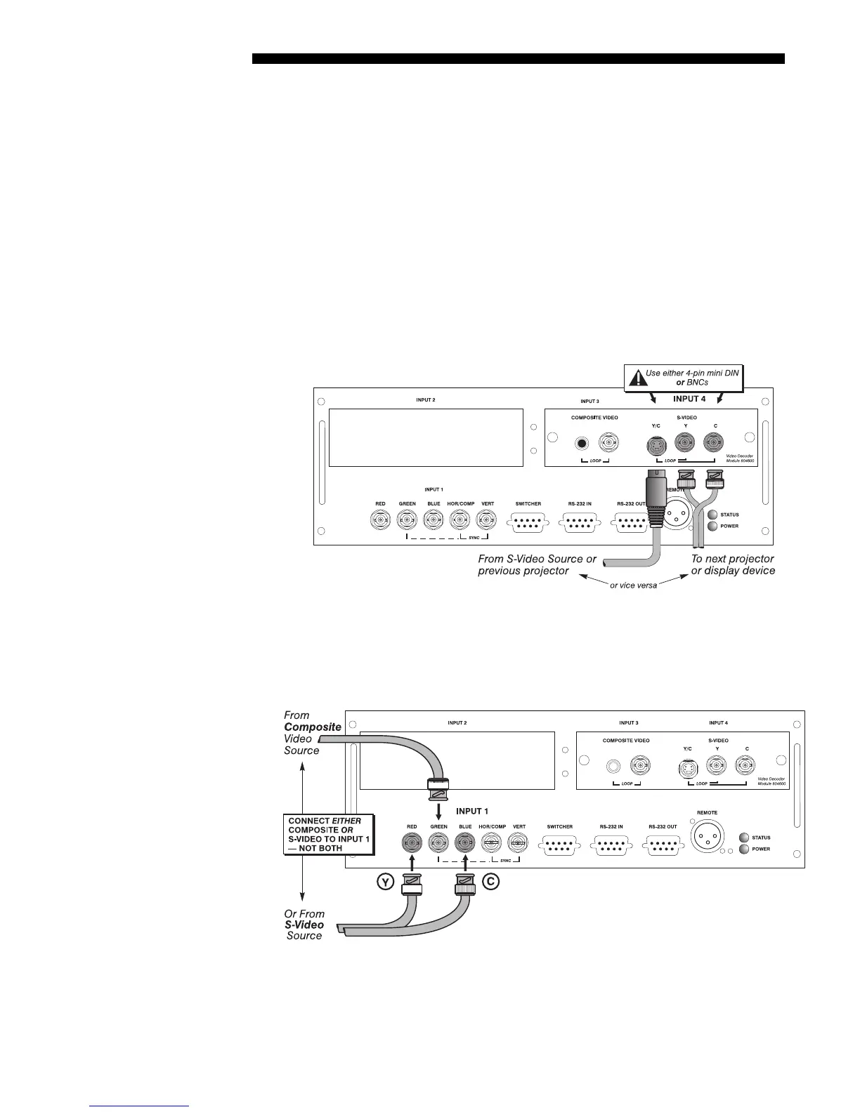
S-Video Loop Through
CONNECTIONS:
See Figure 2.18. From your source, connect an S-video source signal
to
INPUT 4
using either the 4-pin mini DIN or the 2 adjacent BNCs labeled Y and C.
Connect a second cable from whichever
INPUT 4
connector is free to one of the S-
video inputs of the next display device or projector. Continue this looping method for
each projector, using either 4-pin mini DIN or the 2 adjacent BNCs as input into
INPUT 4,
then using the other connector(s) as an output (i.e., loop through). Whether
you use 4-pin mini DIN or the 2 adjacent BNCs as input or output depends on the
type of cable you have on hand and what type of connectors are on each end.
VIDEO TERMINATION:
In the Video Options submenu, make sure “Video
Termination” is checked for only the final projector. All other projectors must have
this option unchecked in order for the signal to continue. For other types of display
devices in the chain, typically a “Hi-Z” switch position is needed.
Figure 2.18. Connections for S-Video Loop Through
If you want to use an extra video source in addition to the video source(s) connected at
INPUT 3 or INPUT 4 connect either a Composite or S-Video source to INPUT 1 as shown in
Figure 2.19. Do not connect both types here simultaneously. NOTE: For additional video
inputs, install an optional Composite/S-Video Input Module at
INPUT 2.
Figure 2.19. Connecting an Extra Video Source to Input 1
Extra Video
'
– COMPOSITE OR S-VIDEO