Front Panel Menu Operation
23
Audible Test
During this test, alarm activation of any input device will activate all signals for one half second.
Trouble activation on any input device will activate all signals continuously for one second.
At this point the display will vary, depending on whether or not a printer is connected to the panel.
If a printer is not connected to the panel, the walk test will print to the display.
• Use and to scroll the cursor through the log.
•Hold INFO ( ) down for more information on the logged event.
Press CANCEL ( ) to exit to the normal system display and clear the Walk Test log.
If a printer is connected to the panel, follow step three, below.
Note: Audible devices connected to an addressable output module will not sound in
Audible Test mode.
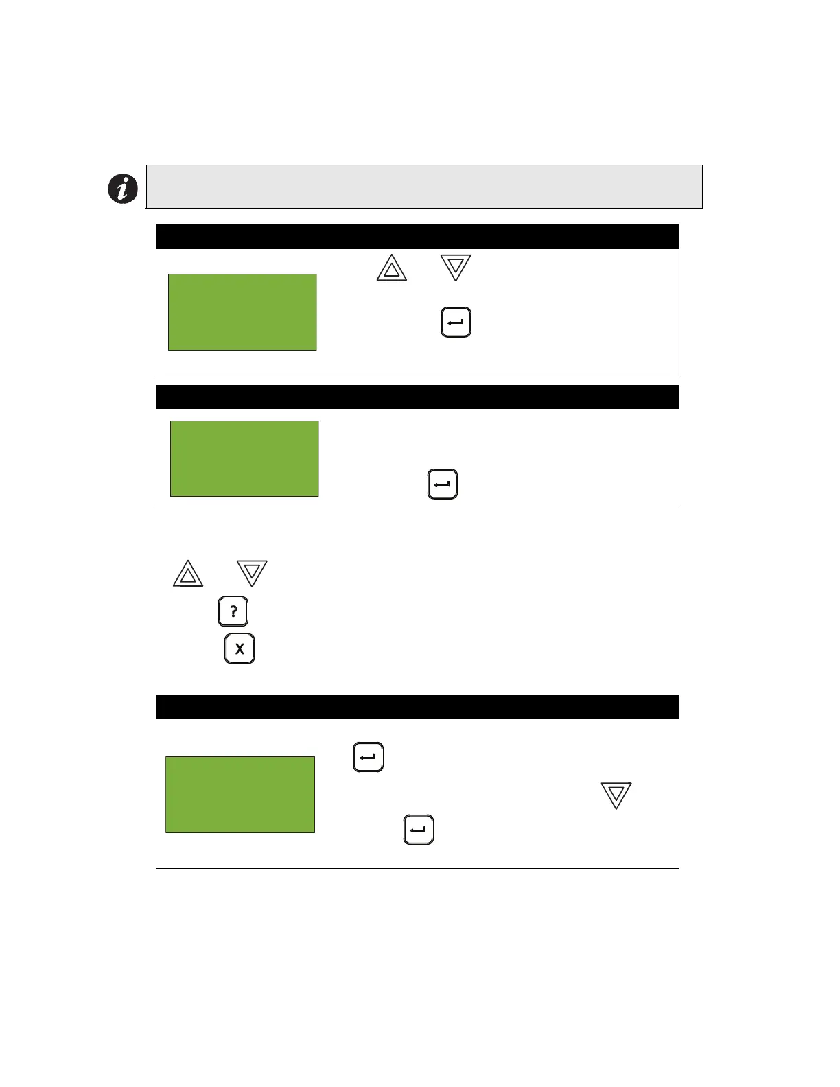
Step 1: Select Audible Test
1. Use and to scroll the cursor to “Audible
Test ” .
2. Press ENTER ( ) when the cursor flashes beside
“Audible Test” to select the Audible Test. The test will
now begin.
Step 2: View the Walk Test
As the test runs, the Alarms and Troubles count will
increase as they are recorded (logged) during the
Audible Test.
Press ENTER ( ) to end the walk test.
Step 3: Print the Walk Test
•To print the Walk Test to the printer, press ENTER
( ) when the cursor flashes beside “Printer”.
•To print the walk test to the screen, press then
ENTER ( ) to select “Screen”. Follow the
instructions above to navigate the Walk Test log.
- Walktest -
1 Audible Test
2 Silent Test
- Walktest
Active -
Alarms: 0
Troubles: 0
- Report to -
1 Printer
2 Screen

 Loading...


