FX-2000 User Guide
4
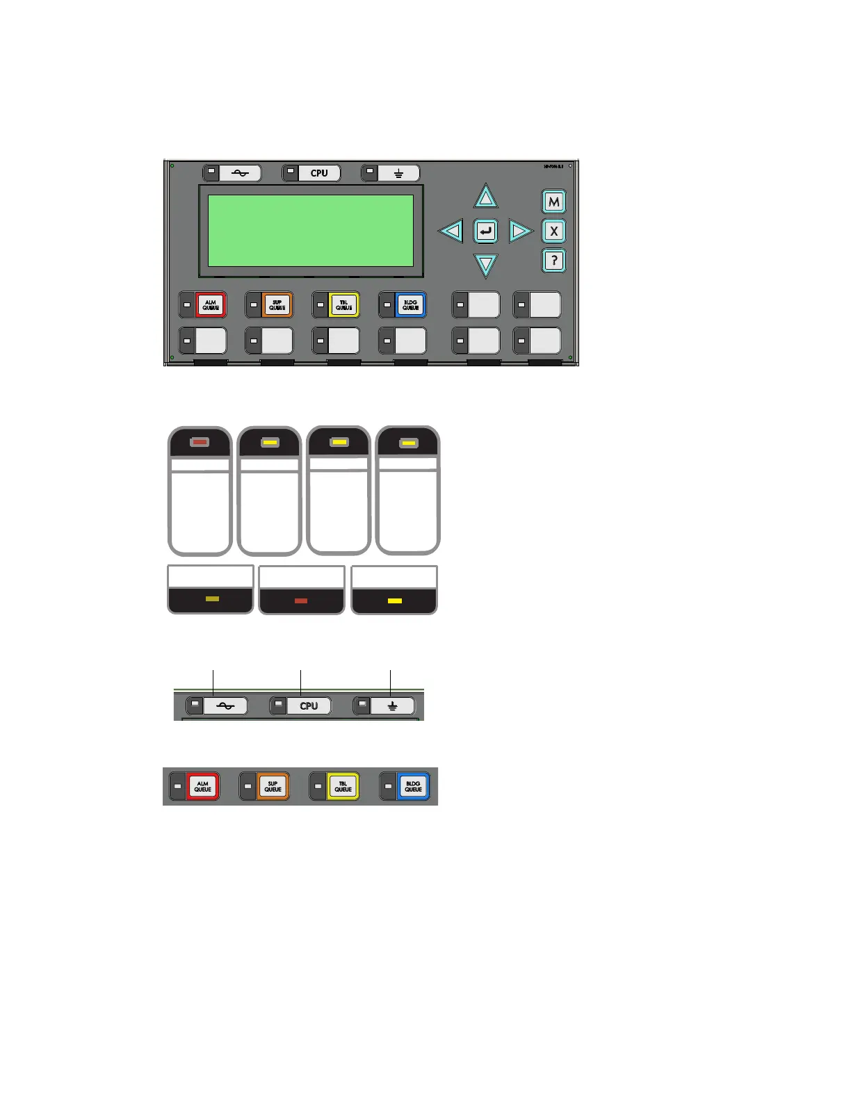
Switch Numbering (New DS Display)
Figure 3 shows the switches as the Configurator numbers them. This display is called 4 x 20
Default in the Configurator.
Figure 3 Switch Numbering for New DS Display
Common Indicators
Figure 4 Classic Display: Common Indicators
Figure 5 New DS Display: AC On, CPU Fault, Ground Fault
Figure 6 New DS Display: Alarm Queue, Supervisory Queue, Trouble Queue, Building
Queue
Buzzer
The buzzer is activated by any of the following:
• Fire alarm: steady
• Supervisory alarm: fast flash rate
• Trouble: trouble flash rate
• Monitor/Building: Configurable to sound at trouble flash rate
If the buzzer turns on in response to a non-latching trouble or supervisory, it will turn off if the
condition causing it goes away and there is no other reason for it to be on.
MCG Network
Fire Control System
- System Normal -
Mar 04, 2014 12:00:00
0
1
2
4
5
67
3
ALARM
QUEUE
SUPV.
QUEUE
TROUBLE
QUEUE
MONITOR
QUEUE
A.C. ON
CPU FAULT
GND FAULT
GROUND FAULTCPU FAULTAC ON

 Loading...


