122
6 USING THE PROGRAMMABLE CONTROLLER CPU MONITORING FUNCTION
6.2 Programmable Controller CPU Monitoring Function
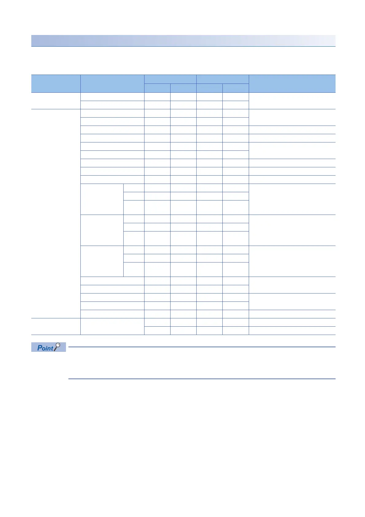
List of device code
The word and bit devices that can be designated as the monitoring targets and the device codes that are used to register the
monitoring devices are listed in the table below.
Register the devices using the device ranges existing in the CPU module.
• Designating a non-existent device code will result in an error.
• When the device range in the parameter setting has been changed, the new device range can be set as the
programmable controller CPU monitoring target.
Category Device Device type Device code Device range (Default)
Bit Word ASCII Binary
Internal system Special relay SM 91H 0 to 4096
Special register SD A9H
Internal user Input X* 9CH 0 to 2FFFH
Output Y* 9DH
Internal relay M* 90H 0 to 12287
Latch relay L* 92H 0 to 8191
Annunciator F* 93H 0 to 2047
Edge relay V* 94H
Link relay B* A0H 0 to 1FFFH
Data register D* A8H 0 to 18431
Link register W* B4H 0 to 1FFH
Timer Contact TS C1H 0 to 1023
Coil TC C0H
Current
value
TN C2H
Retentive timer Contact SS C7H 0
Coil SC C6H
Current
value
SN C8H
Counter Contact CS C4H 0 to 511
Coil CC C3H
Current
value
CN C5H
Link special relay SB A1H 0 to 7FFH
Link special register SW B5H
Direct input DX A2H 0 to 2FFFH
Direct output DY A3H
Index register Z* CCH 0 to 20
Register File register R* AFH 0 to 32767
ZR B0H
 Loading...


