Sistema
α
Alambrado 4
20
ESP
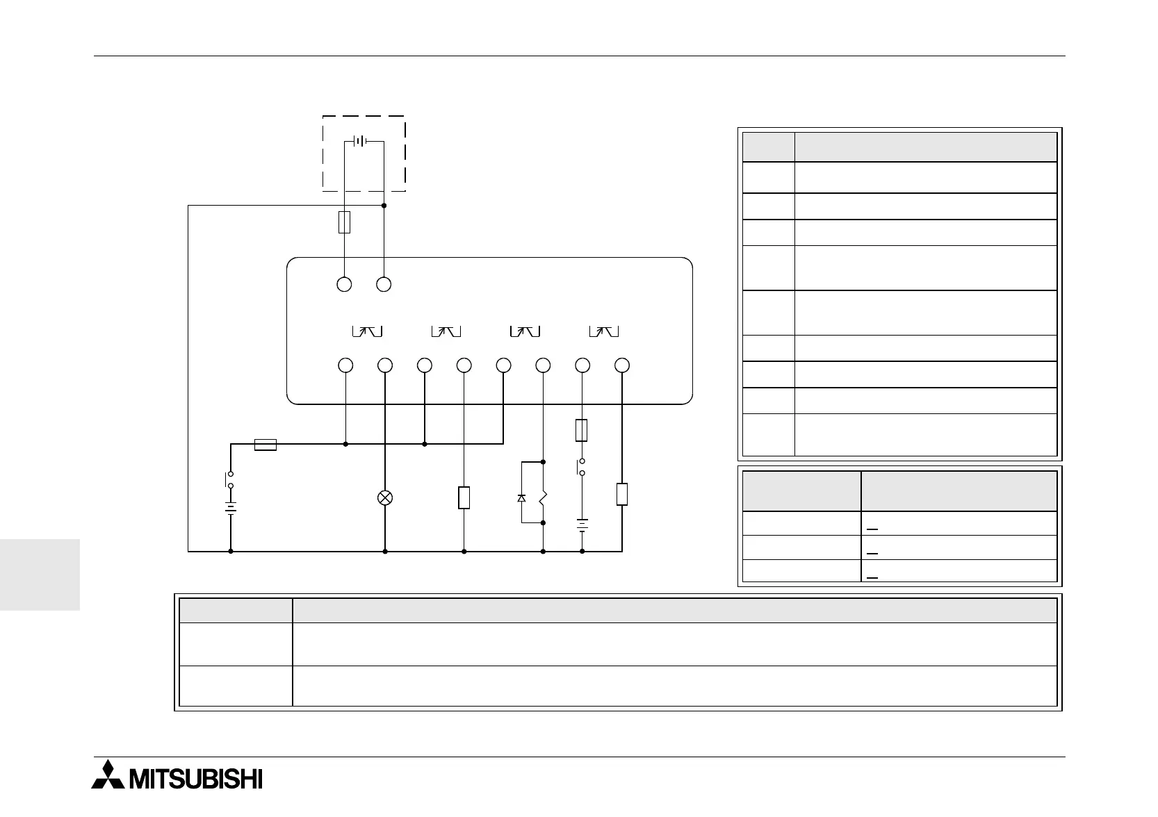
4.7.2 Sortidas de transistor (source o “+” Common solamente)
Tabla 4.5: Sortidas de transistor
No. Description
1
Sistema
α
2 Bornas de entrada
3 Dispositivos de salida
4
Dispositivo de protectción
ver la tabla 4.6
5
Interruptor de parada de
emergencia
6 Alimentación CC para sortidas
7 Bornas de tensión
8 Alimentación CC, 24V CC
9
Dispositivo de protección
con límite de 1,0A
Circuito
Voltaje de la protección
del circuito (fusible)
5 Volt < 0,3 A por circuito
12 Volt <
2,0 A por circuito
24 Volt <
2,0 A por circuito
Volt Bornas de sortidas
5 or 12-24
Cada circuito puede contener desde un terminal de salida hasta cualquier número de termi-
nales de salida.
5,12,24
Cualquier combinación de salidas de 5 , 12 o 24 voltios es posible en un mismo controlador
de la serie
a
si se trabaja con circuitos separados para cada nivel de voltaje..
"
!
OUT1
#
#
OUT2 OUT3 OUT4
$
%
&
+−
+−
(
$
%
&
+
+
#
)
'
 Loading...


