α
Simple Application Controller
Wiring 4
20
ENG
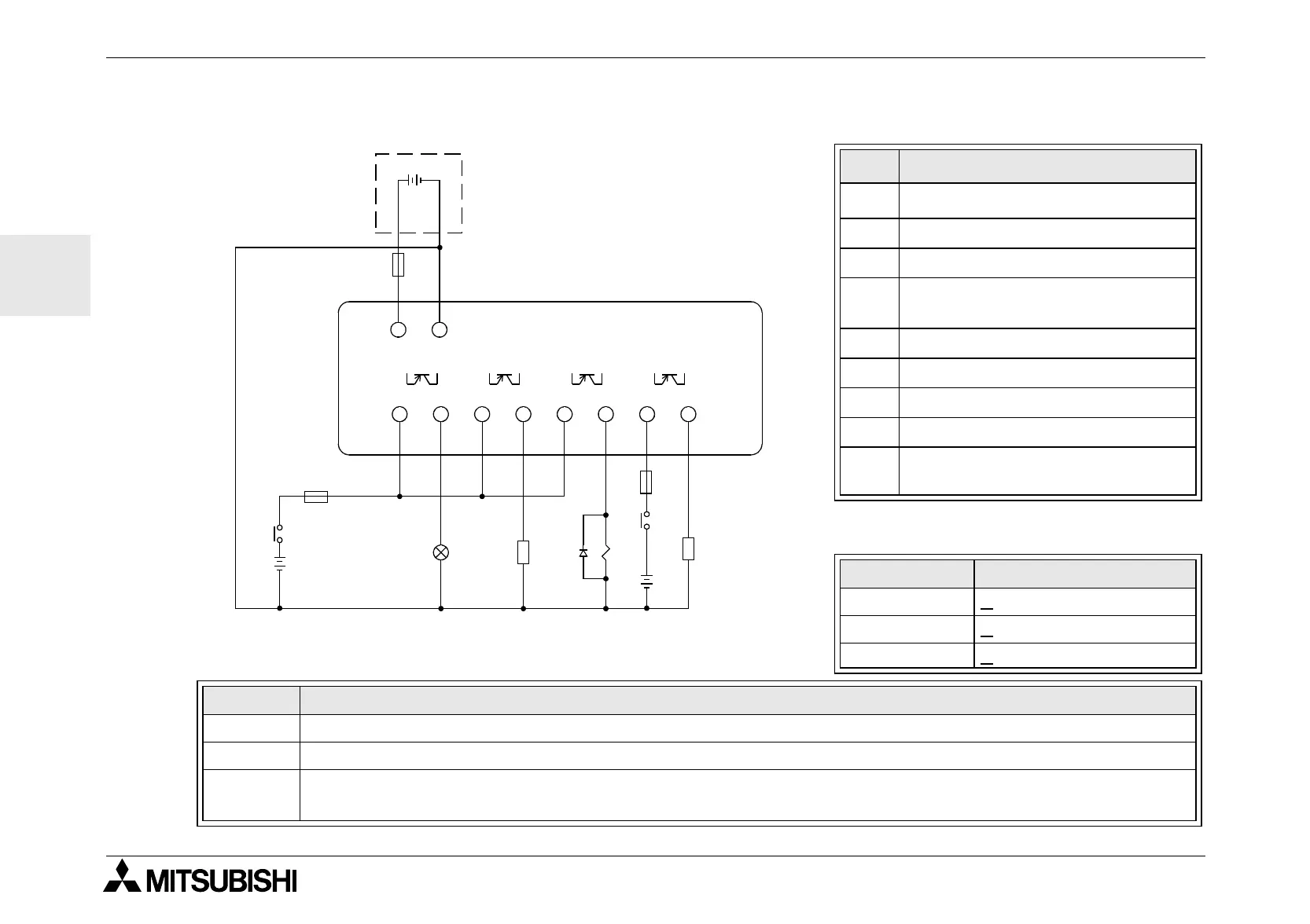
4.7.2 Transistor Output (Source or “+” Common Only) Wiring Diagram
Table 4.5: Transistor Output Wiring
Ref. Item Description
1
α
Base Unit
2 Output Terminals
3 Output Devices
4
Circuit Protection Device - See
Table 4.6 for Specifications
5 Emergency Stop
6 DC Power Supply for output
7Power Terminal
8 DC Power Supply, 24V DC
9
Circuit Protection Device
- Limit to 1.0 Amps
Table 4.6: Transistor Output Circuit
Protection Table
Circuit Voltage Circuit Protection (Fuse)
5 Volt < 0.3 Amps per Circuit
12 Volt <
2.0 Amps per Circuit
24 Volt <
2.0 Amps per Circuit
Volt Output Terminal Notes
5 Each circuit can contain from one output terminal up to every output terminal.
12-24 Each circuit can contain from one output terminal up to every output terminal.
5,12,24
Using any combination of 5 Volt, 12 Volt, and 24 Volt outputs can be accomplished on the same
α
Series Controller if separate circuits are used for each voltage level.
"
!
OUT1
#
#
OUT2 OUT3 OUT4
$
%
&
+−
+−
(
$
%
&
+
+
#
)
'
 Loading...


