α
Simple Application Controller
Wiring 4
16
ENG
4.3 Power Supply
When wiring AC supplies the “Live” cable should be connected to the “L” terminal and the “Neutral” cable
should be connected to the “N” terminal. Do NOT connect the “Live” wire to the “N” terminal, the user might
receive a dangerous shock on powerup.
When wiring DC supplies the “positive” cable should be connected to the "+" terminal and the negative cable
should be connected to the “-” terminal. On no account should the power supply terminals be connected to
any other terminal on the unit. DC Power Supply units should be capable of providing 4 Amperes of current
to the controller.
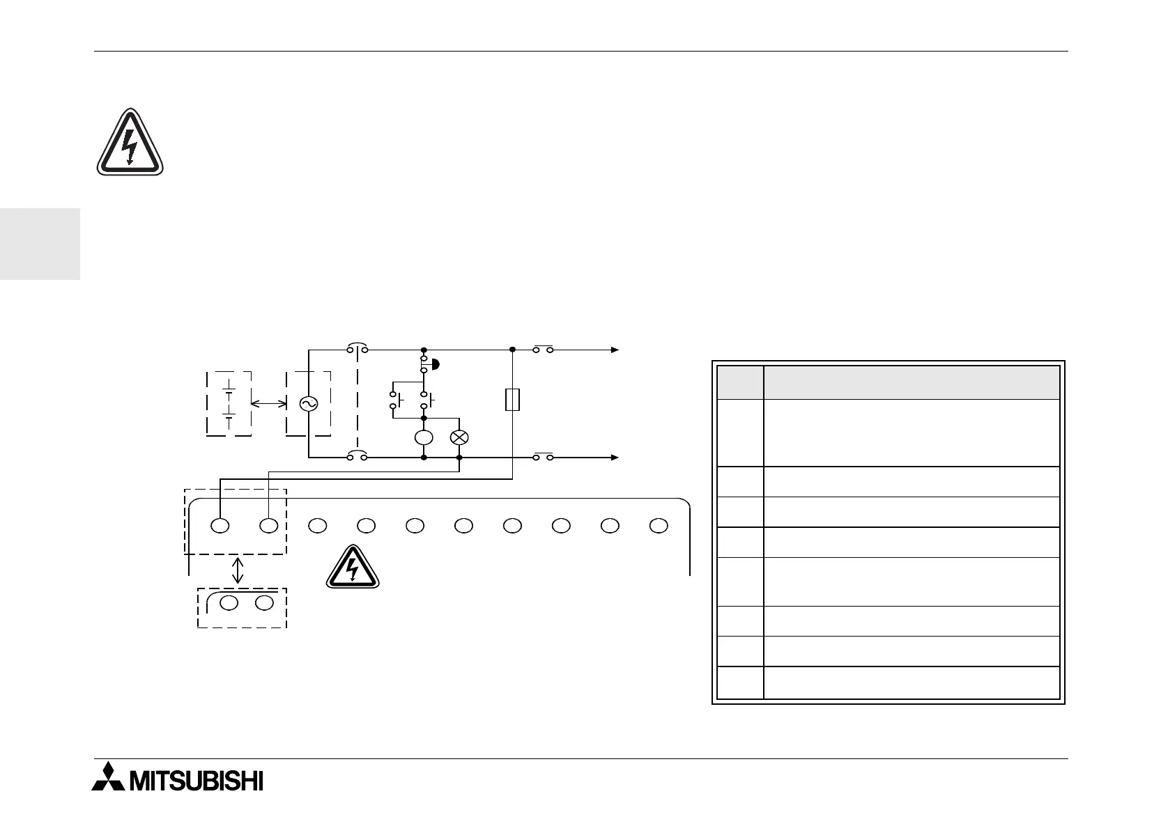
4.4 Recommended Power Input Wiring Diagram
Table 4.1:Recommended Power Wiring
Ref. Item Description
1
Power Supply: AC~:100-240V
50-60Hz
DC: 24V
2 Circuit Isolation Device
3 Emergency Stop
4 Power On Pilot Indicator
5
Circuit protection device - limit to
1.0 Amps
6 Power Supply for AC loads
7 Magnetic Switch Contact
8
α
Base Unit
MC
MC
MC
MC
LN
!"
#
$
%
&
'
(
+
−
L
N
+−
Start
"L" and "N" terminals are not
reversible.
 Loading...


