α
Simple Application Controller
Installation 3
12
ENG
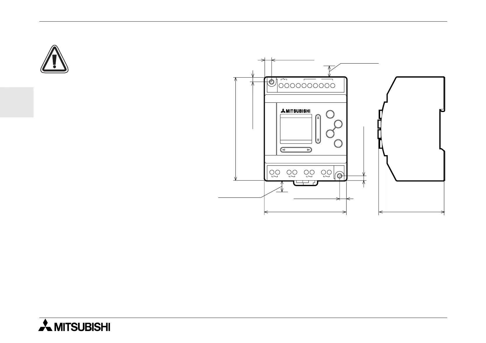
3.3 Installation Mounting Notes
The
α
Series’ safe design means the
user can install it almost anywhere but
the following points should be taken into
consideration.
Do not install in areas with: excessive or
conductive dust, corrosive or flammable
gas, moisture or rain, excessive heat,
regular impact shocks or excessive
vibration. Do not place in water or let
water leak onto the controller.
Do not allow debris to fall inside the unit
during installation.
Keep as far as possible from
high-voltage cables and power equip-
ment.
The
α
Series Controller must be
installed in cabinets which are designed
for the assembly of devices complying
to DIN 43880 or in a control box.
Use size M4 screws when mounting by screw holes.
The connectors must be covered to prevent injury from contact with “live” wires.
* Leave a minimum of 10mm of space for ventilation between the top and bottom edges of the
α
Series Con-
troller and the enclosure walls.
POWER
IN
OK
+
RELAY OUTPUT
ESC
-
34215L6N
OUT3 OUT4OUT2OUT1
AC INPUT
AC 100/240V
10(0.39")*
10(0.39")*
71.2(2.80")
6.0(0.24")
90.0(3.54")
4.0(0.16")
55.0(2.17")
4.0(0.16")
6.0(0.24")
 Loading...


