α
Simple Application Controller
Wiring 4
15
ENG
4. Wiring
4.1 Installation Wiring Notes
The wiring of
α
Series has been designed to be safe and easy. A technician or engineer trained in the local
and national electrical standards should perform all tasks associated with the electrical wiring of the
α
Series
controllers. Turn off the Power before performing any wiring operations.
• Input and output cables should not be run through the same multicore cable or share the same wire.
• Do not lay input/output cables near high voltage power cables.
Allow for voltage drop and noise interference with input/output lines used over an extended distance. Please
use wire that is properly sized for the current load.
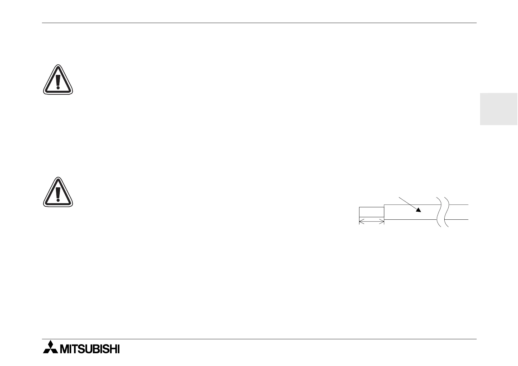
4.2 Wire Size and Specifications
Wire the Inputs and Outputs using 26 - 12 AWG wire (0.13 mm
2
- 3.31
mm
2
). Strip the wire to a length of 7 +- 0.5 mm (0.250 - 0.300 inches).
Please unscrew the terminal to its widest position before inserting a wire.
Insert the wire completely into the terminal to ensure that a proper con-
nection can be made. Insert the wire into the terminal and tighten enough
to keep the wire from pulling free. To avoid damaging the wire, do not
exceed a maximum torque of 0.5 N
⋅
m. Please do not use tin, solder, or
any other substance on the stripped wire that might cause the wire strand
to break.
The terminals will accept a 3mm flathead screwdriver.
7mm(0.276") ± 0.5mm(0.02")
26 -12 AWG
 Loading...


