13
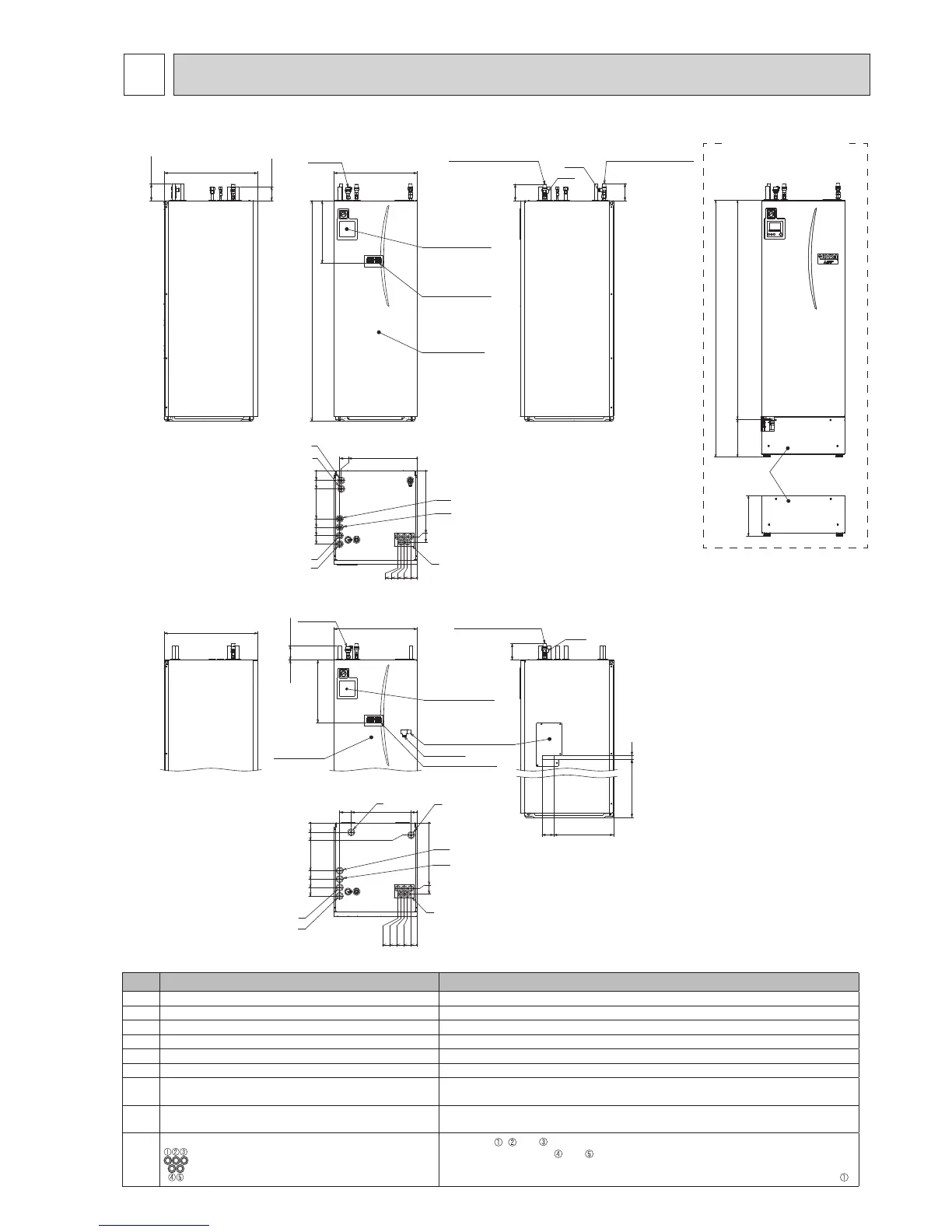
OUTLINES AND DIMENSIONS
5
<Unit: mm>
5-1. Technical Drawings
J
A
C
D
B
F/G
E/H
470.7
510.7
0
67.8
522.3
462.3
402.3
342.3
88.3
0
46.7
136.7
114.2
91.7
69.2
0
42.1
552.7
470.7
0
G1/2
83 427
30863
118
680
CPF 15mm
595
100 ± 20
449
1600
595
1600
449
J
A
B
D
C
F/G
E/H
46.7
136.7
114.2
91.7
69.2
0
67.8
522.3
462.3
402.3
342.3
127.8
0
552.7
542
0
470.7
510.7
0
680
100 ± 20
120 ± 20
G1/2
G1/2
118
123
287.5
1600
270
1870
Letter Pipe description Connection size/type
A DHW outlet connection 22 mm/Compression
B Coldwaterinletconnection 22 mm/Compression
C Spaceheating/coolingreturnconnection 28 mm/Compression
D Spaceheating/coolingowconnection 28 mm/Compression
E Flowfromheatpumpconnection(Noplateheatexchanger) 28 mm/Compression
F Returntoheatpumpconnection(Noplateheatexchanger) 28 mm/Compression
G
Refrigerant(GAS)
(Withplateheatexchanger)
12.7 mm/Flare (E*ST20D-*)
15.88 mm/Flare (E*ST20C-*)
H
Refrigerant(LIQUID)
(Withplateheatexchanger)
6.35 mm/Flare (E*ST20D-*)
9.52 mm/Flare (E*ST20C-*)
J
Electrical cable inlets
For inlets , and ,runlow-voltagewiresincludingexternalinputwiresandther-
mistorwires.Forinlets
and ,runhigh-voltagewiresincludingpowercable,indoor-
outdoorcable,andexternaloutputwires.
*Forawirelessreceiver(option)cableandecodanWi-Fiinterface(option)cable,useinlet .
<Left side> <Front> <Rightside>
<Top>
Air vent
Main remote
controller
Pressure relief valve
(Primary circuit)
Terminal block
Front panel
Temperature and
pressure relief valve
and it's access plate
<E**T20*-*M**C>
<EH*T20*-MHCW>
Pressure relief valve
(Sanitary circuit)
Pressure relief valve
(Primary circuit)
Main remote
controller
Terminal block
<Left side> <Front>
<Rightside>
<Top>
Air vent
Front panel
<Front>
<ERST20*-*M**C>
Optional part
(PAC-DP01-E)

 Loading...
