S1
S2
S3
L
N
L
N
CN01
CN01
CN01
CN01
S1
S2
S3
L
N
S1
S2
S3
S1
S2
S3
TB1
L
N
L
N
ECB1
ECB2
L
N
36
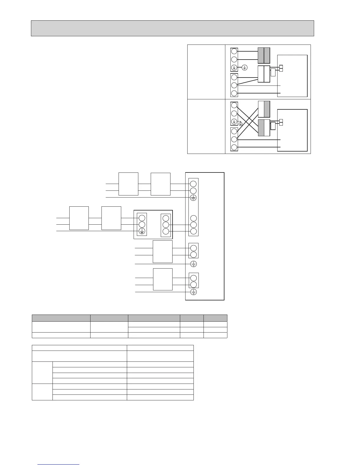
Initialsettings
(Powersuppliedby
outdoor unit)
Modiedsettings
(Separatepower
supply to the cylinder
unit)
Cylinder unit
control board
Cylinder unit
control board
White
BLACK
BLACK
YELLOW
BLACK
YELLOW
YELLOW
YELLOW
BLACK
White
Option2:Cylinderunitpoweredbyindependentsource.
Ifthecylinderunitandoutdoorunithaveseparatepowersupplies,thefollowing
requirements MUST be carried out:
•Changetheinterconnectedwiringinthecontrolandelectricalboxofthe
cylinder unit (see Figure 7-3).
•TurntheoutdoorunitDIPswitchSW8-3toON.
•TurnontheoutdoorunitBEFOREthecylinderunit.
•Powerbyindependentsourceisnotavailableforparticularmodelsof
outdoor unit model. For more detail, refer to the connecting outdoor unit
Installation Manual.
Wiring
circuit
breaker
or
Isolating
switch
Power
supply
~/N
230 V
50Hz
Earth
leakage
circuit
breaker
*
1,
*
2
Earth
leakage
circuit
breaker
*
1,
*
2
Wiring
circuit
breaker
or
Isolating
switch
Power
supply
~/N
230 V
50Hz
Outdoor unit
Cylinder unit
Power
supply
~/N
230 V
50Hz
Power
supply
~/N
230 V
50Hz
Wiring
circuit
breaker
or
Isolating
switch
Wiring
circuit
breaker
or
Isolating
switch
For
booster
heater
(Primary circuit)
For
Immersion
heater
(DHW tank)
To control
board
<1 phase>
<Figure7-4>
Electrical connections 1 phase
<Figure7-3>
Description Power supply Capacity Breaker Wiring
Booster heater (Primary circuit) ~/N230V50Hz 2 kW 16 A
*
2
2.5 mm²
6 kW 32 A
*
2
6.0 mm²
Immersion heater (DHW tank) ~/N230V50Hz 3 kW 16 A
*
2
2.5 mm²
Cylinderunitpowersupply ~/N230V50Hz
Cylinder unit input capacity
Mainswitch(Breaker)
*
2
16 A
Wiring
WiringNo.
×size(mm²)
Cylinderunitpowersupply 2 × Min. 1.5
Cylinderunitpowersupplyearth 1 × Min. 1.5
Cylinder unit - Outdoor unit
*
3
2 × Min. 0.3
Cylinder unit - Outdoor unit earth —
Circuit
rating
Cylinder unit L - N
*
4
230 V AC
Cylinder unit - Outdoor unit S1 - S2
*
4
—
Cylinder unit - Outdoor unit S2 - S3
*
4
24 V DC
*
2
Abreakerwithatleast3.0mmcontactseparationineachpoleshallbeprovided.Useearthleakagebreaker(NV).
The breaker shall be provided to ensure disconnection of all active phase conductors of the supply.
*
3
Maximum120m
*
4
Thevaluesgiveninthetableabovearenotalwaysmeasuredagainstthegroundvalue.
Notes: 1. Wiring size must comply with the applicable local and national codes.
2.Indoorunit/outdoorunitconnectingcordsshallnotbelighterthanpolychloroprenesheathedexiblecord.(Design60245IEC57)
Indoorunitpowersupplycordsshallnotbelighterthanpolychloroprenesheathedexiblecord.(Design60227IEC53)
3. Install an earth line longer than power cables.
4.
Please keep enough output capacity of power supply for each heater.
Insufcientpowersupplycapacitymightcausechattering.
*
1
Iftheinstalledearthleakagecircuitbreaker
does not have an over-current protection
function,installabreakerwiththatfunction
alongthesamepowerline.
AffixlabelBthatisincludedwiththemanuals near
eachwiringdiagramforcylinderunitandoutdoorunits.

 Loading...
