16
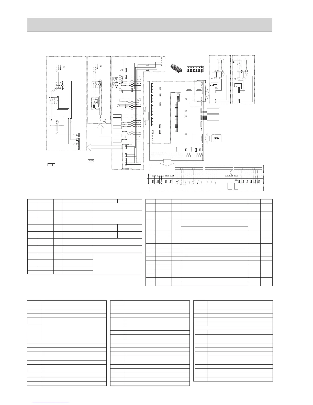
6-2. EHST20C-VM2CR1.UK, EHST20C-VM2ECR1.UK, EHST20D-VM2CR1.UK, EHPT20X-VM2CR1.UK,
EHST20D-VM2ECR1.UK, ERST20C-VM2CR1.UK, ERST20D-VM2CR1.UK
1
3
5
7
X6
X7
1
3
1
3
CNBHT
(BK)
CNBC
(GY)
CNBH
(WH)
NL
S3S2S1
NL
S3S2S1
To outdoor
unit
TB1
OG
OG
YE
YE
GNYE
To outdoor
unit
Power supply
~/N 230V 50Hz
TB1
OG
BU
RD
BU
RD
YE
GNYE
1
3
CN3C
(BU)
BK
BK
BK
BK
1
3
OG
BN
CN3C
(BU)
OG
OG
BN
YE
Indoor unit powered
by independent source
Indoor unit powered
via outdoor unit
CIRCUIT
BREAKER
1
3
CN3C
(BU)
1
3
CNPWM
(WH)
LED1
LED2
LED3
LED4
TBI.1
TBI.2
1310 12 141174 65 932 811310 12 141174 65 932 811310 12 141174 65 932 81
IN6
IN1
IN2
IN3
IN4
IN5
IN7
THW8
THW7
THW6
THW9
THWB1
THWB2
t
°
t
°
t
°
t
°
t
°
t
°
Main remote
controller
1
+
-
+
-
+
-
2
1
2
CN20
(RD)
TH1
t
°
1
3
CN21
(YE)
TH2
t
°
1
4
THW1
THW2
CNW12
(RD)
t
°
t
°
Flow
Sensor
1
4
CN1A
(WH)
1
2
THW5
CNW5
(WH)
t
°
CN108
5
1
Wireless receiver
(Option)
WiFi adapter
(Option)
5
1
5
1
CNRF
(WH)
CN105
(RD)
CN22
(BU)
1
3
5
Close
Open
N
X15
X12
TBO.3
TBO.2
TBO.1
F1
F2
MXV
M
1
~
MP2
MP1
M
1
~
CNV1
(WH)
X11
X10
X4
X14
X3
X2
X1
X5B
X5A
1
2
3
4
5
6
7
8
1
2
3
4
5
6
1
2
3
4
5
6
1
1
3
3
3
CNP1
(WH)
CNP4
(RD)
CNPWM
(WH)
TBO.1
TBO.2
TBO.3
TBO.4
CNP1
(WH)
CNP4
(RD)
CNV1
(WH)
CN22
(BU)
CNIT
(BU)
TAB1
CN01
(WH)
F2 F1
IEC T6.3AL250V IEC T10AL250V
SW1
SW2
SW3
SW4
SW5
1
8
1
8
1
1
3
5
1
3
1
3
8
1
8
1
6
CN01
(WH)
CN01
(WH)
2
1
4
6
2
1
1
2
4
6
4
6
CNBH
(WH)
CNBC
(GY)
1
1
3
1
2
1
2
1
2
CNBHT
(BK)
1
3
7
1
3
CNIH
(OG)
1
4
1
3
CNW5
(WH)
CN21
(YE)
CNW12
(RD)
CN20
(RD)
TBI.2
MP3
M
1
~
IN8
IN9
IN10
TBI.3
TBI.3
1
4
CN1A
(WH)
TBI.1
2WV2b
M
1
~
M
1
~
MP4
M
1
~
1
3
L
(1)
N
(3)
OG
RD
BU
BU
RD
OG
IHC
IHT
IH
642
531
A1
A2
A B
2
4
Immersion heater (1Ph3kW)(Option)
Power supply
to Immersion heater
~/N 230V 50Hz
1
2
CNIH
(OG)
3
3WV
M
1
~
Signal output
(Boiler)
Signal output
(Error)
Signal output
(Defrost)
Signal output
(Comp. ON)
Signal output
(Cooling)
ECB2
1
2
4
6
CN01
(WH)
WH
WH
2 2
2
ECB1
L
(1)
N
(3)
BHCP
BU
BU
RD
WH/No.2
WH/No.1
RD
VT
VT
GY
GY
BHC1
BHT
642
531
A1
A2
BH1
BHF
2
4
Power supply
to Booster heater
642
531
A1
A2
CNBH
(WH)
CNBHT
(BK)
2
2
2
CNBC
(GY)
1
1
3
3
1
3
~/N 230V 50Hz
1
2
3
4
5
6
TBO.4
M
2WV2a
1
3
X9
X8
X13
CNIH
(OG)
1
2
3
4
5
6
1
2
3
4
5
6
1
2
3
4
5
6
7
8
1
2
3
4
5
6
12 146 108
137 119
4
53
2
1
12 146 108
137 119
4
53
2
1
12 146 108
137 119
4
53
2
1
Tool
Tool
Conductor
Conductor
Outline view Top view
<How to use TBO.1 to 4>
Connect them using either way as shown below.
Table 1 Signal Inputs
Name
Terminal block
Connector
Item OFF (Open) ON (Short)
IN1 TBI.1 13-14 —
Room thermostat 1
input
Refer to SW2-1 in
<6-19.DIPswitchfunctions>.
IN2 TBI.1 11-12 — Flowswitch1input
Refer to SW2-2 in
<6-19.DIPswitchfunctions>.
IN3 TBI.1 9-10 —
Flowswitch2input
(Zone1)
RefertoSW3-2in<6-19.DIPswitch
functions>.
IN4 TBI.1 7-8 — Demand control input Normal
Heat source OFF/
Boiler operation *2
IN5 TBI.1 5-6 —
Outdoor thermostat
input *1
Standard opera-
tion
Heater operation/
Boiler operation *2
IN6 TBI.1 3-4 —
Room thermostat 2
input
Refer to SW3-1 in
<6-19.DIPswitchfunctions>.
IN7 TBI.1 1-2 —
Flowswitch3input
(Zone2)
Refer to SW3-3 in
<6-19.DIPswitchfunctions>.
IN8 TBI.3 1-2 —
Electricenergymeter
1
Refer to installation manual.
IN9 TBI.3 3-4 —
Electricenergymeter
2
IN10
TBI.3 5-6 — Heat meter
IN1A
TBI.3 12-14 CN1A Flowsensor
*1.Ifusingoutdoorthermostatforcontrollingoperationofheaters,thelifetimeofthe
heaters and related parts may be reduced.
*2. To turn on the boiler operation, use the main remote controller to select “Boiler” in
“Externalinputsetting”screenintheservicemenu.
Table 2 Outputs
Name
Terminal block
Connector
Item OFF ON
OUT1
TBO.1 1-2 CNP1
Watercirculationpump1output(Spaceheating/
cooling&DHW)
OFF ON
OUT2
TBO.1 3-4 —
Watercirculationpump2output(Spaceheating/
coolingforZone1)
OFF ON
OUT3
TBO.1 5-6 —
Watercirculationpump3output(Spaceheating/
coolingforZone2)*1
OFF ON
2-wayvalve2boutput*2
OUT4
TBO.2 4-6 CNV1 3-wayvalveoutput Heating DHW
OUT5
TBO.2 1-2
— Mixingvalveoutput*1 Stop
Close
TBO.2 2-3 Open
OUT6
—
CNBH 1-3
Booster heater 1 output OFF ON
OUT7
—
CNBH 5-7
Booster heater 2 output OFF ON
OUT8
TBO.4 5-6 — Coolingsignaloutput OFF ON
OUT9
TBO.4 3-4 CNIH Immersion heater output OFF ON
OUT10
TBO.3 1-2 — Boiler output OFF ON
OUT11
TBO.3 3-4 — Error output Normal Error
OUT12
TBO.3 5-6 — Defrost output Normal Defrost
OUT13
TBO.4 1-2 — 2-wayvalve2aoutput*2 OFF ON
OUT14
— CNP4 Water circulation pump 4 output (DHW) OFF ON
OUT15
TBO.3 7-8 — Comp.ONsignal OFF ON
Donotconnecttotheterminalsthatareindicatedas“—”inthe“Terminalblock”eld.
*1.For2-zonetemperaturecontrol.
*2.For2-zonevalveON/OFFcontrol.
1.Symbolsusedinwiringdiagramare, :
connector,
: terminal block.
2.Indoorunitandoutdoorunitconnectingwires
have polarities, make sure to match terminal
numbers(S1,S2,S3)forcorrectwirings.
3.Sincetheoutdoorunitsideelectricwiringmay
change,besuretochecktheoutdoorunit
electricwiringdiagramforservice.
Symbol Name
TB1 Terminalblock<Powersupply,Outdoorunit>
ECB1
Earthleakagecircuitbreakerforboosterheater
ECB2
Earthleakagecircuitbreakerforimmersionheater
MP1 Water circulation pump 1
(Spaceheating/cooling&DHW)
MP2 Water circulation pump 2
(Spaceheating/coolingforZone1)(Localsupply)
MP3 Water circulation pump 3
(Spaceheating/coolingforZone2)(Localsupply)
MP4 Water circulation pump 4 (DHW)
3WV 3-wayvalve
2WV2a 2-wayvalve(ForZone1)(Localsupply)
2WV2b 2-wayvalve(ForZone2)(Localsupply)
MXV Mixingvalve(Localsupply)
BHT Thermostat for booster heater
BHF Thermal fuse for booster heater
BH1 Booster heater 1
BHC1 Contactor for booster heater 1
BHCP Contactor for booster heater protection
IHT Thermostat(xedtemp.)forimmersionheater
Symbol Name
IH Immersion heater
IHC Contactor for immersion heater
TH1 Thermistor (Room temp.)(Option)
TH2 Thermistor (Ref. liquid temp.)
THW1 Thermistor(Flowwatertemp.)
THW2 Thermistor(Returnwatertemp.)
THW5 Thermistor(DHWtankwatertemp.)
THW6 Thermistor(Zone1owtemp.)(Option)
THW7 Thermistor (Zone1 return temp.)(Option)
THW8 Thermistor(Zone2owtemp.)(Option)
THW9 Thermistor (Zone2 return temp.)(Option)
THWB1 Thermistor(Boilerowtemp.)(Option)
THWB2 Thermistor (Boiler return temp.)(Option)
IN1 Room thermostat 1 (Local supply)
IN2 Flowswitch1(Localsupply)
IN3 Flowswitch2(Localsupply)
IN4 Demand control (Local supply)
IN5 Outdoor thermostat (Local supply)
IN6 Room thermostat 2 (Local supply)
Symbol Name
IN7 Flowswitch3(Localsupply)
IN8 Electricenergymeter1(Localsupply)
IN9 Electricenergymeter2(Localsupply)
IN10 Heat meter (Local supply)
IN1A Flowsensor
FLOW TEMP. CONTROLLER (FTC5)
TBO.1-4
Terminal block <Outputs>
TBI.1-3 Terminalblock<SignalInputs,Thermistor>
F1 Fuse (IEC T10AL250V)
F2 Fuse (IEC T6.3AL250V)
SW1-5 DIPswitch*See<6-19.DIPswitchfunctions>.
X1-15 Relay
LED1 Powersupply(FTC5)
LED2 Powersupply(Mainremotecontroller)
LED3 Communication (FTC5-Outdoor unit)
LED4 ReadingorwritingdatatoSDcard
CNPWM
PumpspeedcontrolsignalforMP1
CN108 SD card connector

 Loading...
