64
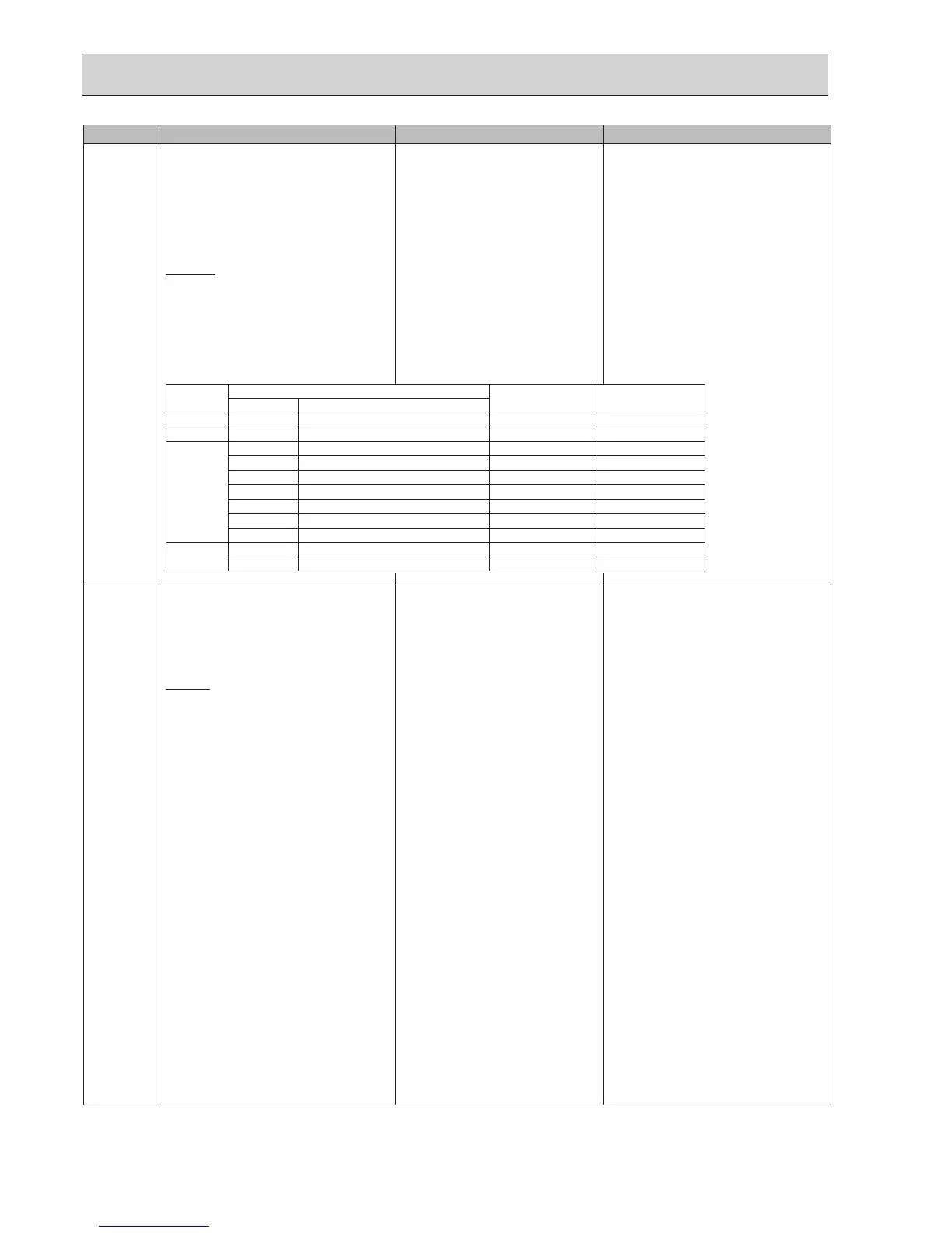
Error code Title and display conditions Possible Cause Diagnosis and action
P1/P2/L5/LD
Indoor unit temperature thermistor failure
Note:Thethermistorssubjecttofailurecanbe
checked in “Request code: 567” in
“Runninginformation.
<DHW/Heating/Cooling/LP/FS/OS>
Errorcodedisplayedwhenthermistorisatopenor
short (see table).
Exceptions
Error code will not be displayed for TH2; During
defrost and for 10 minutes after defrost operation.
Error code
Thermistor
Open detection Short detection
Symbol Name
P1 TH1A/TH1B Room temperature thermistor −39ºCorbelow 88.5ºCorabove
P2 TH2 Liquid temperature thermistor −39ºCorbelow 88.5ºCorabove
L5
THW1 Flowwatertemperaturethermistor −39ºCorbelow 88.5ºCorabove
THW2 Returnwatertemperaturethermistor −39ºCorbelow 88.5ºCorabove
THW5 Tankwatertemperaturethermistor −39ºCorbelow 88.5ºCorabove
THW6
Zone1owwatertemperaturethermistor
−39ºCorbelow 88.5ºCorabove
THW7
Zone1returnwatertemperaturethermistor
−39ºCorbelow 88.5ºCorabove
THW8
Zone2owwatertemperaturethermistor
−39ºCorbelow 88.5ºCorabove
THW9
Zone2returnwatertemperaturethermistor
−39ºCorbelow 88.5ºCorabove
LD
THWB1
Boilerflowwatertemperaturethermistor
−40ºCorbelow 140ºCorabove
THWB2
Boilerreturnwatertemperaturethermistor
−40ºCorbelow 140ºCorabove
1. Connector/terminalwirehasbecome
detachedorloosewiring.
1. Visually check the terminals and connec-
tions and reattaches appropriate.
2. Thermistor fault 2. Checkresistanceofthermistoragainst
tablein"10-6.CheckingComponentParts'
Function".
Compare FTC detected temperature to
hand held detector.
3. FTC board failure 3. Replace board.
4. Thethermistoronthewirelessremote
controller or the main remote control-
lermaybedefective.(whenRoom
temp.ischosenfortheHeatingopera-
tionandwhenMainremotecontroller
or Room RC 1-8 is chosen for the
RoomSensorsettingintheInitial
setting)
4. Replacewirelessremotecontrollerormain
remote controller.
5. IncorrectsettingoftheDIPswitch(es) 5. ChecktheDIPswitchsetting(s).
L6
Circulation water freeze protection
<DHW/Heating/Cooling/LP/FS/OS>
ErrorcodedisplayedwhenTHW1detectsa
temp.≤1ºCfor10consecutivesecondsor
THW2detectsatemp.≤3ºCfor10consecutive
seconds.
Exception
Errorcodewillnotbedisplayedif;
FS function is disabled,
For10minutesafterwatercirculationpump1is
switchedon.
1. Insufcientsystemhead 1. Refertotablein"10-6.CheckingCompo-
nentParts'Function"todetermineifsystem
pump meets requirements.
If more head required either add a pump of
thesamesizeorreplaceexistingpumpwith
capacity model.
See"11.DISASSEMBLYPROCEDURE"for
howtoreplacepump.
2. Reducedowinprimarywatercircuit
Dueto1ormoreofthefollowing;
Faultypump,insufcientairpurge,
blockedstrainer,leakinwatercircuit
2. Checkcirculationpump(See"10-6.
CheckingComponentParts'Function"for
howtocheck).
Openpurgevalvetoremovetrappedair.
Checkthestrainerforblockages.
Checktheprimarywatercircuitforleaks.
Checkthattheowamountiswithinthe
recommendedrange.
3. Valve operation fault 3. Checkvalvesonprimarywatercircuitare
installed level.
4. 2-wayvalve(localsupply)actuator
fault
4. Electrically test to determine fault.
5. 3-wayvalveactuatorfault 5. 1) Electrically test to determine fault.
2)Operate3-wayvalvemanuallyusingthe
main remote controller. (Refer to
<Manualoperation>in"9-4.Service
menu".)
3)Replace3-wayvalvecoil.
4)Replace3-wayvalve.(RefertoProcedure
6 in “11. DISASSEMBLY PROCEDURE”.)
6. THW1 has become detached from its
holder.
6. Visually inspect location and reattach as
necessary.
7. THW1 or THW2 fault 7. Checkresistanceofthermistoragainsttable
in"10-6.CheckingComponentParts'
Function".
Compare FTC detected temperature to
hand held detector.
8. FTC board failure 8. Replace board.

 Loading...
