70
No. Fault symptom Possible cause Explanation - Solution
4 LED2 on FTC is off.
(See"6.WIRING
DIAGRAM".)
<FTCpoweredonindependentsource>
1. FTCisnotsuppliedwith220to240VAC. 1. CheckthevoltageacrosstheLandNterminalsontheindoorpowersupply
terminalblock.(See"7.FIELDWIRING".)
•Whenthevoltageisnot220to240VAC,checkforfaultywiringtopower
supply.
•Whenthevoltageis220to240VAC,goto2.below.
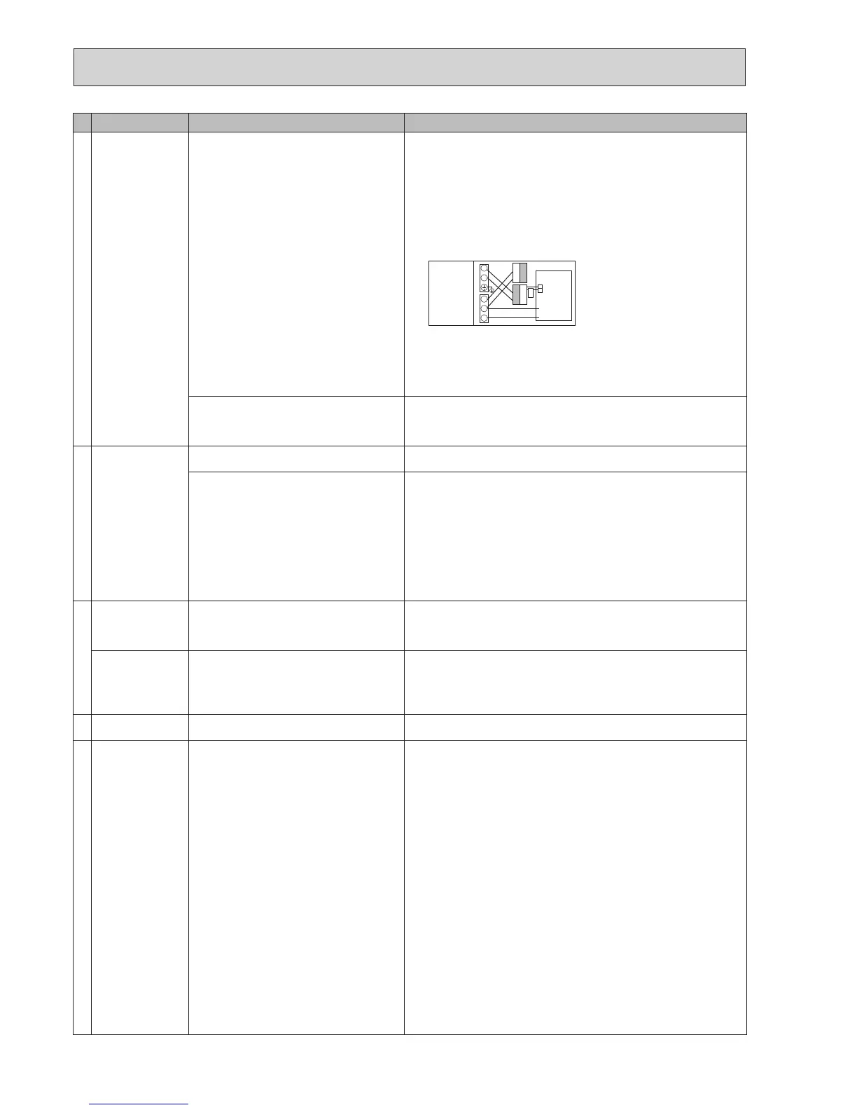
2. There are problems in the method of
connectingtheconnectors.
2. Checkforfaultywiringbetweentheconnectors.
•Whentheconnectorsarewiredincorrectlyre-wirethem correctlyreferring
tobelow.(See"7.FIELDWIRING"andawiringdiagramonthecontroland
electricalboxcover.)
L
N
CN01
CN01
S1
S2
S3
•Ifnoproblemfoundwiththewiring,goto3.below.
3. FTC failure 3. Check the FTC control board.
•CheckthefuseonFTCcontrolboard.
•Checkforfaultywiring.
•Ifnoproblemfoundwiththewiring,theFTCcontrolboardisfaulty.
When LED1 on FTC is lit. Rechecktherefrigerantaddresssettingontheoutdoorunit.
Settherefrigerantaddressto“0”.
(SetrefrigerantaddressusingSW1(3-6)onoutdoorcontrollercircuitboard.)
Incorrectsettingofrefrigerantaddressfor
outdoor unit.
(Noneoftherefrigerantaddressissetto"0".)
5 LED2 on FTC is
blinking.
(See"6.WIRING
DIAGRAM".)
WhenLED1isalsoblinkingonFTC. CheckforfaultywiringbetweenFTCandoutdoorunit.
FaultywiringbetweenFTCandoutdoorunit
When LED1 on FTC is lit.
1. Faultywiringinmainremotecontroller
Multipleindoorunitshave been wired to a
singleoutdoorunit.
1. Checkforfaultywiringinmainremotecontroller.
Thenumberofindoorunitsthatcanbewiredtoasingleoutdoorunitisone.
Additionalindoorunitsmustbewiredindividuallytoasingleoutdoorunit.
2. Short-circuitedwiringinmainremotecontrol-
ler
2.,3.
Removemainremotecontroller wires and check LED2 on FTC.(See"6.
WIRINGDIAGRAM".)
•
IfLED2isblinkingcheckforshortcircuitsinthemainremotecontrollerwiring.
•IfLED2islit,wirethemainremotecontrolleragainand:
-ifLED2isblinking,themainremotecontrollerisfaulty;
-
ifLED2islit,faultywiringofthemainremotecontrollerhasbeencorrected.
3. Main remote controller failure
6 LED4 on FTC is off.
(See"6.WIRING
DIAGRAM".)
1. SD memory card is NOT inserted into the
memorycardslotwithcorrectorientation.
1. Correctly insert SD memory card in place until a click is heard.
2. Not an SD standards compliant memory card. 2. Use an SD standards compliant memory card. (Refer to installation manual,
"5.8UsingSDmemorycard".)
LED4 on FTC is
blinking.
(See"6.WIRING
DIAGRAM".)
1. Full of data. 1. Moveordeletedata,orreplaceSDmemorycardwithanewone.
2. Write-protected. 2. Releasethewrite-protectswitch.
3. NOT formatted. 3. Refertoinstallationmanual,"5.8UsingSDmemorycard".
4. FormattedinNTFSlesystem. 4. FTCis Notcompatible withNTFSlesystem.UseanSDmemorycardfor-
mattedinFATlesystem.
7 Nowaterathottap. 1. Cold main off 1. Check and open stop cock.
2. Strainer (local supply) blocked. 2. Isolatewatersupplyandcleanstrainer.
8 Coldwaterattap. 1. Hotwaterrunout. 1. EnsureDHWmodeisoperatingandwaitforDHWtanktore-heat.
2. Prohibit, schedule timer or holiday mode se-
lected or demand control input (IN4) or smart
gridready(switch-offcommand).
2. Checksettingsandchangeasappropriate.
3. Heatpumpnotworking. 3. Check heat pump – consult outdoor unit service manual.
4. Booster heater cut-out trip
ped
. 4. Check booster heater thermostat and press reset button if safe.
Resetbuttonislocatedonthesideofboosterheater,coveredwithwhiterub-
bercap.See"4.PARTNAMESANDFUNCTIONS"tondoutitsposition.
5.
Theearthleakagecircuitbreakerforbooster
heater breaker (ECB1) tripped.
5. Check the cause and reset if safe.
6. The booster heater thermal cut-out has
trippedandcannotberesetusingthemanual
reset button.
6. Check resistance across the thermal cut-out, if open then the connection is
brokenandtheboosterheaterwillhavetobereplaced.
Contact your Mitsubishi Electric dealer.
7. Immersion heater cut-out tripped. 7. Check immersion heater thermostat and press reset button, located on im-
mersionheaterboss,ifsafe.If the heater has been operated with no water
insideitmayhavefailed,sopleasereplaceitwithanewone.
8.
Immersion heater breaker (ECB2) tripped.
8. Check the cause and reset if safe.
9. 3-wayvalvefault 9. Checkplumbing/wiringto3-wayvalve.
(i)Manuallyoverride3-wayvalveusingthemainremotecontroller.(Referto
<Manualoperation>in"9-4.Servicemenu")Ifthevalvedoesnotstillfunc-
tion,goto(ii)below.
(ii)Replace3-wayvalvecoil.Ifthevalvedoesnotstillfunction,goto(iii)be-
low.
(iii)Replace3-wayvalve.(Referto"11.DISASSEMBLYPROCEDURE".)
YELLOW
YELLOW
BLACK
BLACK
Modiedsettings
(Separatepower
supply to the
cylinder unit)
Cylinder unit
control board
White

 Loading...
