PROTECTIVE FUNCTIONS
150
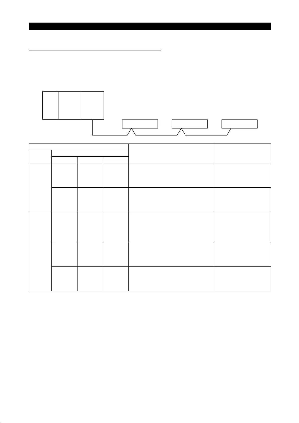
(2) Connection of two or more inverters
The following example indicates the causes and corrective actions for faults which
may be judged from the operating status indicator LED states of the inverters under
the condition that the SW, M/S and PRM LEDs of the master unit are off (the
master unit setting is correct) in the following system configuration.
CPUPower
supply
Master
unit
Station 1
Inverter A
Station 2
Inverter B
Station 3
Inverter C
LED States
Remote I/O unit
Master
unit
Station 1 Station 2 Station 3
Cause Corrective Action
L. RUN
!
SD
!
RD
!
L. ERR
#
L. RUN
!
SD
!
RD
!
L. ERR
#
L. RUN
!
SD
!
RD
!
L. ERR
#
Normal
TIME
#
LINE
#
or
TIME
!
LINE
#
L. RUN
#
SD
#
RD
#
L. ERR
#
L. RUN
!
SD
!
RD
!
L. ERR
#
L. RUN
!
SD
!
RD
!
L. ERR
#
Since the LEDs of station 1 inverter are
all off, 5V power is not supplied or
voltage is insufficient.
Check the voltage of the
24V power supply and
supply normal power to
the inverter.
L. RUN
!
SD
!
RD
!
L. ERR
#
L. RUN
#
SD
*
RD
*
L. ERR
#
L. RUN
#
SD
*
RD
*
L. ERR
#
Since the L.RUN LEDs of station 2
inverter and later are off, the
transmission cable between inverters A
and B is open or disconnected from the
terminal block.
Referring to the LED "on"
condition, search for an
open point and repair.
L. RUN
#
SD
*
RD
*
L. ERR
#
L. RUN
#
SD
*
RD
*
L. ERR
#
L. RUN
#
SD
*
RD
*
L. ERR
#
The transmission cable is shorted.
Among the three wires of
the transmission cable,
search for the shorted wire
and repair.
TIME
!
LINE
!
or
TIME
#
LINE
!
L. RUN
#
SD
*
RD
*
L. ERR
*
L. RUN
#
SD
*
RD
*
L. ERR
*
L. RUN
#
SD
*
RD
*
L. ERR
*
The transmission cable is wired
improperly.
Check the wiring on the
inverter terminal block and
correct the improper wiring
point.
!
: On,
#
: Off,
"
: Flicker,
*
: Any of on, flicker or off

 Loading...


