PROTECTIVE FUNCTIONS
151
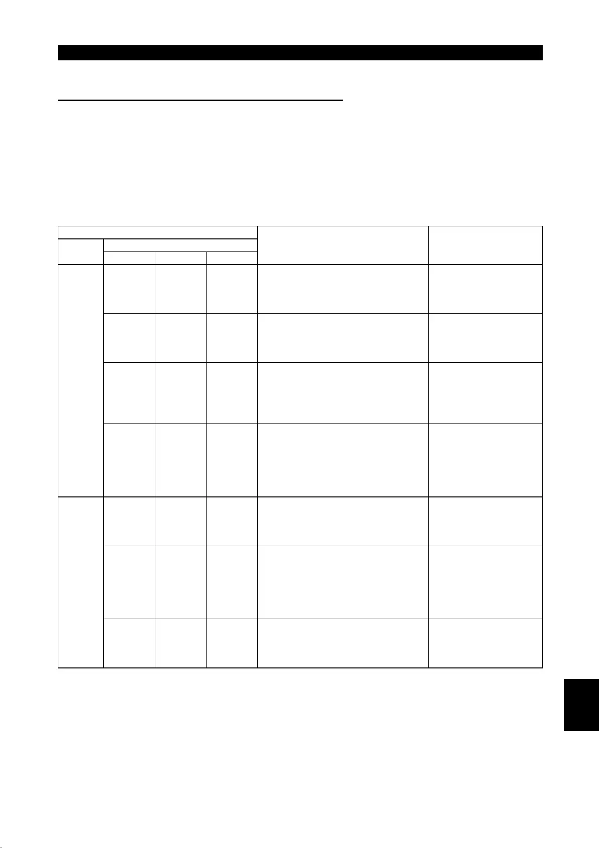
(3) Communication stops during operation
$
Check that the inverters and CC-Link dedicated cable are fitted properly.
(Check for contact fault, open cable, etc.)
$
Check that the programmable controller program is executing reliably and that
the PC CPU is running.
$
Check that data communication has not stopped due to an instantaneous power
failure, etc.
LED States
Remote I/O unit
Master
unit
Station 1 Station 2 Station 3
Cause Corrective Action
L. RUN
#
SD
*
RD
!
L. ERR
#
L. RUN
!
SD
!
RD
!
L. ERR
#
L. RUN
#
SD
*
RD
!
L. ERR
#
Since the L.RUN LEDs of station 1
inverter and station 3 inverter are off, the
station numbers of the inverters set as
stations 1 and 3 are the same.
After correcting the
repeated station numbers
of the inverters, switch
power on again.
L. RUN
!
SD
!
RD
!
L. ERR
#
L. RUN
#
SD
#
RD
!
L. ERR
#
L. RUN
!
SD
!
RD
!
L. ERR
#
Since the L.RUN and SD LEDs of station
2 inverter are off, the transmission speed
setting of station 2 inverter is wrong
within the setting range (0 to 4).
After correcting the
transmission speed
setting, switch power on
again.
L. RUN
!
SD
!
RD
!
L. ERR
#
L. RUN
!
SD
!
RD
!
L. ERR
#
L. RUN
!
SD
!
RD
!
L. ERR
"
Since the L.ERR LED of station 3
inverter flickers, the setting switch of
station 3 inverter was moved during
normal operation.
After returning the setting
switch of the inverter to
the original position,
switch on the inverter
again.
TIME
#
LINE
#
or
TIME
!
LINE
#
L. RUN
#
SD
#
RD
!
L. ERR
!
L. RUN
!
SD
!
RD
!
L. ERR
#
L. RUN
!
SD
!
RD
!
L. ERR
#
Since the L.RUN and SD LEDs of station
1 inverter are off and its L.ERR LED is
on, the setting switch setting of station 1
inverter is outside the range
(transmission speed: 5 to 9, station
number: 65 or more).
After correcting the setting
switch position of the
inverter, switch power on
again.
L. RUN
!
SD
!
RD
!
L. ERR
#
L. RUN
!
SD
!
RD
!
L. ERR
#
L. RUN
!
SD
!
RD
!
L. ERR
#
Since the L.ERR LED of station 2
inverter is on, station 2 inverter itself is
affected by noise. (L.RUN may go off.)
Securely connect FG of
each inverter and master
unit to ground.
L. RUN
!
SD
!
RD
!
L. ERR
#
L. RUN
!
SD
!
RD
!
L. ERR
!
L. RUN
!
SD
!
RD
!
L. ERR
!
Since the L.ERR LEDs of station 2
inverter and later are on, the
transmission cable between station 2
and 3 inverters is affected by noise.
(L.RUN may go off.)
Check that the
transmission cable is
connected to SLD. Also
run it as far away as
possible from the power
lines. (100mm or more)
TIME
!
LINE
!
or
TIME
!
LINE
#
L. RUN
!
SD
!
RD
!
L. ERR
#
L. RUN
!
SD
!
RD
!
L. ERR
#
L. RUN
!
SD
!
RD
!
L. ERR
!
Terminal resistors are left unconnected.
(L.RUN may go off.)
Check that the terminal
resistors are connected.
!
: On,
#
: Off,
"
: Flicker,
*
: Any of on, flicker or off
5

 Loading...


