INSTALLATION AND WIRING
41
!
!!
! Installation and selection of no-fuse breaker
Install a no-fuse breaker (NFB) in the power supply side for protection of the inverter's
primary wiring. Refer to the previous table and choose the NFB according to the
inverter's power supply side power factor (which changes with the power supply
voltage, output frequency and load). Especially for a completely electromagnetic type
NFB, the one with a larger capacity must be selected since its operational
characteristics change with harmonic currents. (Check the data of the corresponding
breaker for confirmation.) Also, the earth leakage circuit breaker used should be
durable against harmonic/surge (such as Progressive Super Series).
!
!!
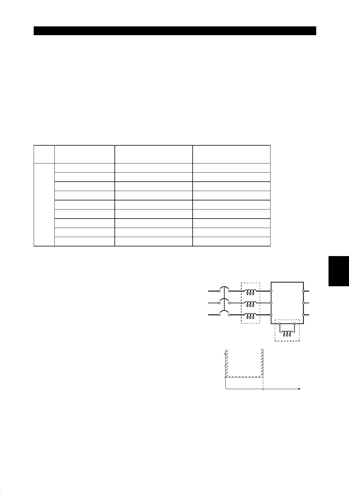
! Power factor improving reactor
Inverter Model
Power Factor
Improving AC Reactor
Power Factor
Improving DC Reactor
FR-E520-0.1KN FR-BAL-0.4K (Note 1) FR-BEL-0.4K (Note 1)
FR-E520-0.2KN FR-BAL-0.4K (Note 1) FR-BEL-0.4K (Note 1)
FR-E520-0.4KN FR-BAL-0.4K FR-BEL-0.4K
FR-E520-0.75KN FR-BAL-0.75K FR-BEL-0.75K
FR-E520-1.5KN FR-BAL-1.5K FR-BEL-1.5K
FR-E520-2.2KN FR-BAL-2.2K FR-BEL-2.2K
FR-E520-3.7KN FR-BAL-3.7K FR-BEL-3.7K
FR-E520-5.5KN FR-BAL-5.5K FR-BEL-5.5K
Three-phase 200V
FR-E520-7.5KN FR-BAL-7.5K FR-BEL-7.5K
Note:1. The power factor may be slightly lower.
When the inverter is connected near a large-
capacity power supply transformer (500kVA
or more, wiring length 10m maximum) or
there is power capacitor switch-over,
excessive peak currents may flow into the
power input circuit and damage the converter
circuit. In such a case, the power supply
improving reactor (FR-BEL or FR-BAL) must
be installed.
NFB
InverterFR-BAL
Power
uppl
R
S
TZ
Y
X
R(L
1
)
S(L
2
)
T(L
3
)
U
V
W
P1P
Power
factor
improving
reactor
range
010
500
1500
1000
Power
supply
capacit
(kVA)
Wiring length(m)
2

 Loading...


