INSTALLATION AND WIRING
42
(
2
)
Selecting the rated sensitivity current for the earth leakage circuit
breaker
When using the earth leakage circuit breaker with the inverter circuit, select its rated
sensitivity current as follows, independently of the PWM carrier frequency:
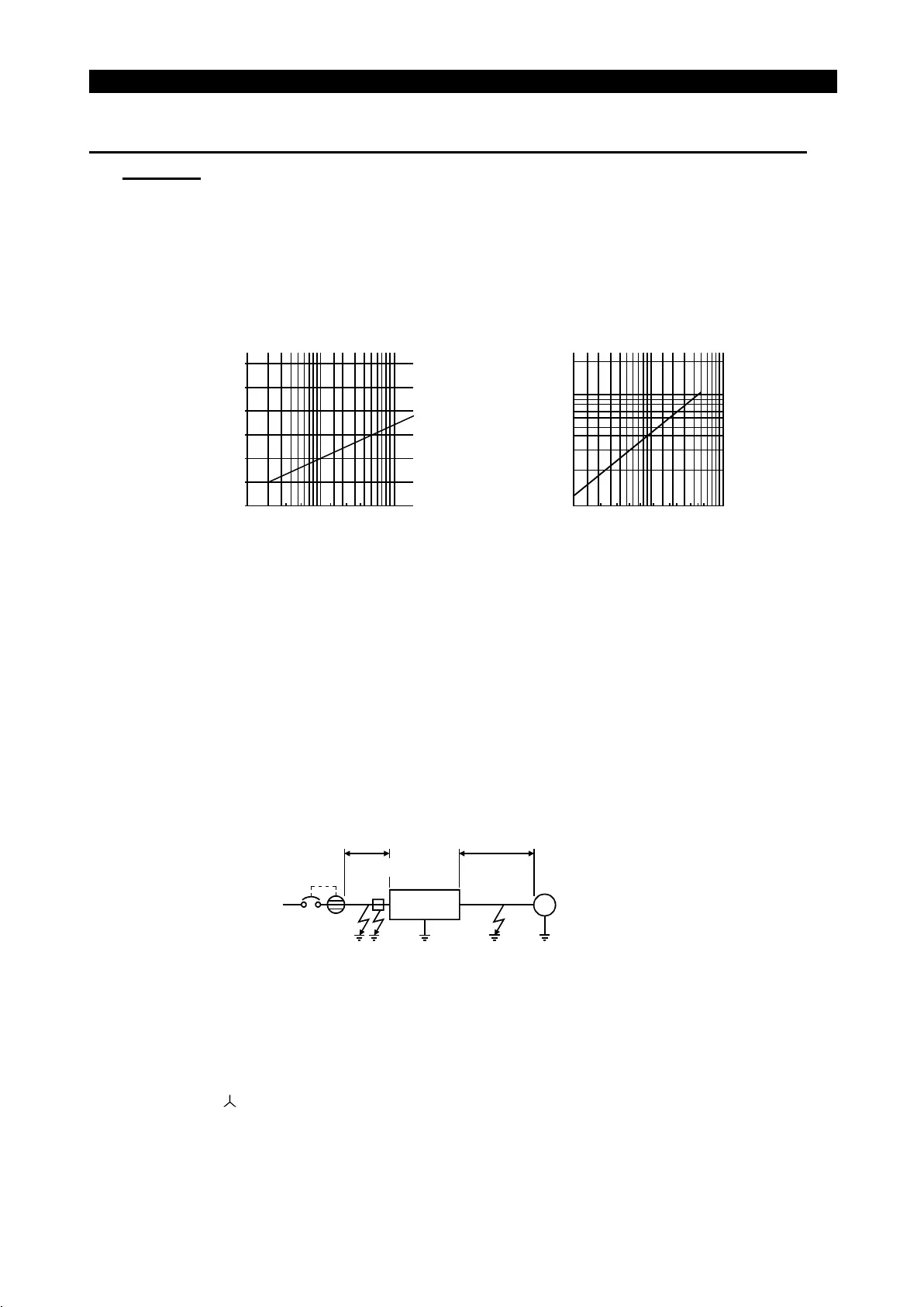
Leakage current example of 3-phase
induction motor during commercial
power supply operation (200V 60Hz)
Example of leakage current per 1kW in
cable path during commercial power
supply operation when the CV cable is
routed in metal conduit
(200V 60Hz)
0
20
40
60
80
100
120
2
3.5
5.5
8
14
22
30
38
60
80
100
150
Cable size (mm
2
)
Leakage current(mA)
0.1
1.5
2.2 7.5
15
11
37
30 55
0.2
0.3
0.5
0.7
1.0
2.0
18.5
Motor capacity (kW)
Leakage current(mA)
45
3.7
5.5
22
"
Progressive Super Series (Type SP, CF, SF, CP)
Rated sensitivity current: I
∆
n
≥
10
×
(lg1+Ign+lg2+lgm)
"
Conventional NV series (Type CA, CS, SS produced prior to '91)
Rated sensitivity current: I
∆
n
≥
10
×
{lg1+lgn+3
×
(lg2+lgm)}
lg1, lg2 : Leakage currents of cable path during commercial power supply operation
lgn* : Leakage current of noise filter on inverter input side
lgm : Leakage current of motor during commercial power supply operation
<Example>
Ig1 Ign Ig2 Igm
5.5mm
2
×
5m 5.5mm
2
×
70m
IM
3
φ
200V 2.2kW
Inverter
NV
Noise filter
Note:1. The earth leakage circuit breaker should be installed to the primary (power
supply) side of the inverter.
2. Ground fault in the secondary side of the inverter can be detected at the
running frequency of 120Hz or lower.
3. In the
connection neutral point grounded system, the sensitivity current is
purified against ground fault in the inverter secondary side. Hence, the
protective grounding of the load equipment should be 10
Ω
or less.

 Loading...


