457
FX3G/FX3U/FX3GC/FX3UC Series
Programming Manual - Basic & Applied Instruction Edition
16 External FX Device – FNC 80 to FNC 89
16.4 FNC 83 – HEX / ASCII to Hexadecimal Conversion
11
FNC30-FNC39
Rotation and
Shift
12
FNC40-FNC49
Data Operation
13
FNC50-FNC59
High-Speed
Processing
14
FMC60-FNC69
Handy
Instruction
15
FNC70-FNC79
External FX I/O
Device
16
FNC80-FNC89
External FX
Device
17
FNC100-FNC109
Data
Transfer 2
18
FNC110-FNC139
Floating Point
19
FNC140-FNC149
Data
Operation 2
20
FNC150-FNC159
Positioning
Control
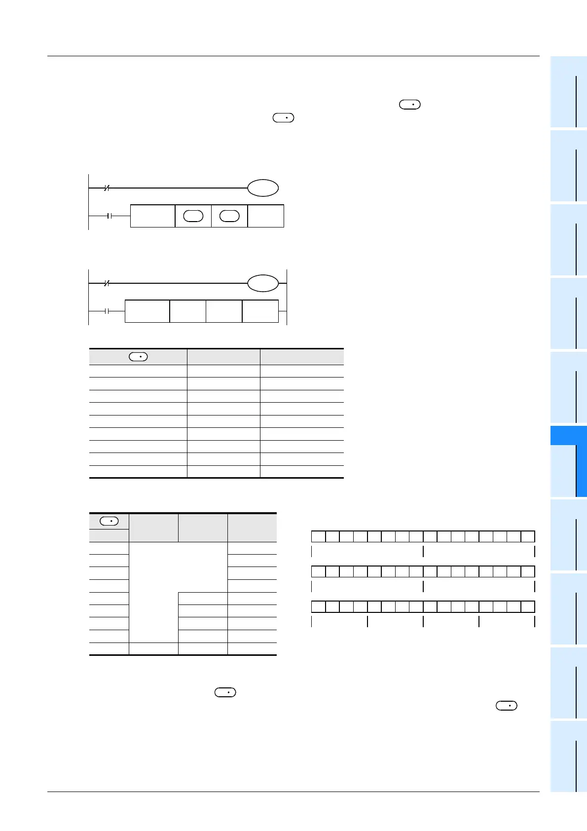
2. 16-bit conversion mode (while M8161 is OFF)
(M8161 is used also for the RS, ASCI, CCD, and CRC instructions.)
Each ASCII code stored in high-order 8 bits and low-order 8 bits of devices and later is converted into a
hexadecimal code, and transferred to devices and later in units of 4 digits. The number of characters to be
converted is specified by "n".
M8161 is used also for the RS, ASCI, CCD and CRC instructions. When using the 16-bit mode, set M8161 to normally
OFF.
M8161 is cleared when the PLC mode is changed from RUN to STOP.
Operation
In the following program, conversion is executed as follows:
Conversion source data
Number of specified characters and conversion result
" • " indicates "0".
• When the input data is in BCD format, it is necessary to convert BCD data into binary data after executing this
instruction.
• If ASCII code is not stored in in the HEX instruction, an operation error occurs and conversion into
hexadecimal code is disabled. Especially, note that ASCII code should be stored in high-order 8 bits of also
when M8161 is OFF.
ASCII code Hexadecimal code
Low-order 8 bits of D200 30H 0
High-order 8 bits of D200 41H A
Low-order 8 bits of D201 42H B
High-order 8 bits of D201 43H C
Low-order 8 bits of D202 31H 1
High-order 8 bits of D202 32H 2
Low-order 8 bits of D203 33H 3
High-order 8 bits of D203 34H 4
Low-order 8 bits of D204 35H 5
D 102 D 101 D 100
n
1
Does not change
•••0H
2 ••0AH
3 •0ABH
4 0ABCH
5 •••0H ABC1H
6 ••0AH BC12H
7 •0ABH C123H
8 0ABCH 1234H
9 •••0H ABC1H 2345H
S
D
M8161
M8000
FNC 83
HEX
nS
Command
input
D
16-bit mode
M8161
M8000
FNC 83
HEX
D200 D100 K4
X010
16-bit mode
S
0011110101010000
D 100
0ABC
In the case of "n = K4"
0000110010000010
D 200
41H
→
[A] 30H
→
[0]
0100001011000010
D 201
43H
→
[C] 42H
→
[B]
D
S
S

 Loading...


