839
FX3G/FX3U/FX3GC/FX3UC Series
Programming Manual - Basic & Applied Instruction Edition
37 Operation of Special Devices (M8000 -, D8000 -)
37.1 Special Device List (M8000 -, D8000 -)
31
FNC276-FNC279
Data
Transfer 3
32
FNC280-FNC289
High-Speed
Processing 2
33
FNC290-FNC299
Extension File
Register
34
FNC300-FNC305
FX
3U
-CF-ADP
35
SFC•STL
Programming
36
Interrupt
Function
37
Special Device
38
Error Code
A
Version Up
Information
B
Execution Times
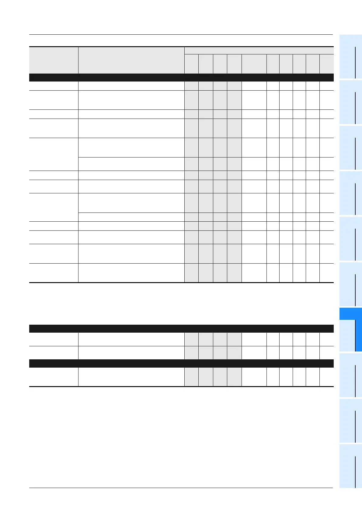
Inverter Communication Function (Refer to Data Communication Edition for details.)
D 8150
*1
Response wait time of inverter communication [ch1]
3
*4
3 3 3 – –––– –
[D]8151
Step number of instruction during inverter
communication [ch1]
Default: -1
3
*4
3 3 3 M8151 – – – – –
[D]8152
*2
Error code for inverter communication [ch1]
3
*4
3 3 3 M8152 – – – – –
[D]8153
*2
Inverter communication error step number
latched [ch1]
Default: -1
3
*4
3 3 3 M8153 – – – – –
[D]8154
*2
Parameter number when error occurs during
IVBWR (FNC274) instruction [ch1]
Default: -1
– – 3 3 M8154 – – – – –
Response waiting time of EXTR (FNC180)
instruction
– – – ––––
3
*3
–
3
*3
D 8155
*1
Response wait time of inverter communication [ch2]
3
*4
3 3 3 – –––– –
[D]8155
Step number during communication of EXTR
(FNC180) instruction
– – – – M8155 – –
3
*3
–
3
*3
[D]8156
Step number of instruction during inverter
communication [ch2]
Default: -1
3
*4
3 3 3 M8156 – – – – –
Error code for EXTR (FNC180) instruction
– – – – M8156 – –
3
*3
–
3
*3
[D]8157
*2
Error code for inverter communication [ch2]
3
*4
3 3 3 M8157 – – – – –
[D]8157
Error step (latched) for EXTR (FNC180) instruction
Default: -1
– – – – M8157 – –
3
*3
–
3
*3
[D]8158
*2
Inverter communication error step number
latched [ch2]
Default: -1
3
*4
3 3 3 M8158 – – – – –
[D]8159
*2
Parameter number when error occurs during
IVBWR (FNC274) instruction [ch2]
Default: -1
– – 3 3 M8159 – – – – –
*1. Cleared when PLC power supply is turned from OFF to ON.
*2. Cleared when PLC switches from STOP to RUN.
*3. Available in Ver. 3.00 or later.
*4. Available in Ver. 1.10 or later.
Display Module Function [FX1S and FX1N]
D 8158
FX1N-5DM: Control device (D)
Default: -1
– – – ––33 –––
D 8159
FX1N-5DM: Control device (M)
Default: -1
– – – ––33 –––
FX1N-BAT [FX1N] (Refer to FX1N-BAT Manual for details.)
D 8159
Specification of low battery voltage detection flag
for the FX1N-BAT
Default: -1
– – – –––3 –––
Number and name Content of register
Applicable model
FX
3G
FX
3GC
FX
3U
FX
3UC
Correspond-
ing special
device
FX
1S
FX
1N
FX
2N
FX
1NC
FX
2NC

 Loading...


