8. MICROCOMPUTER MODE
8 − 12
MELSEC-A
Device
CPU
Type
Address Configuration
Input (X)
8000
H
to
80FF
H
X0 to 7FF
Output
(Y)
8200
H
to
82FF
H
Y0 to 7FF
Internal
relay (M)
Latch
relay (L)
Step
relay (S)
8400
H
to
84FF
H
M/L/S
0 to 2047
Link
relay (B)
8600
H
to
867F
H
B0 to 3FF
Annuci-
ator (F)
A3H
A3M
8700
H
to
871F
H
F0 to 255
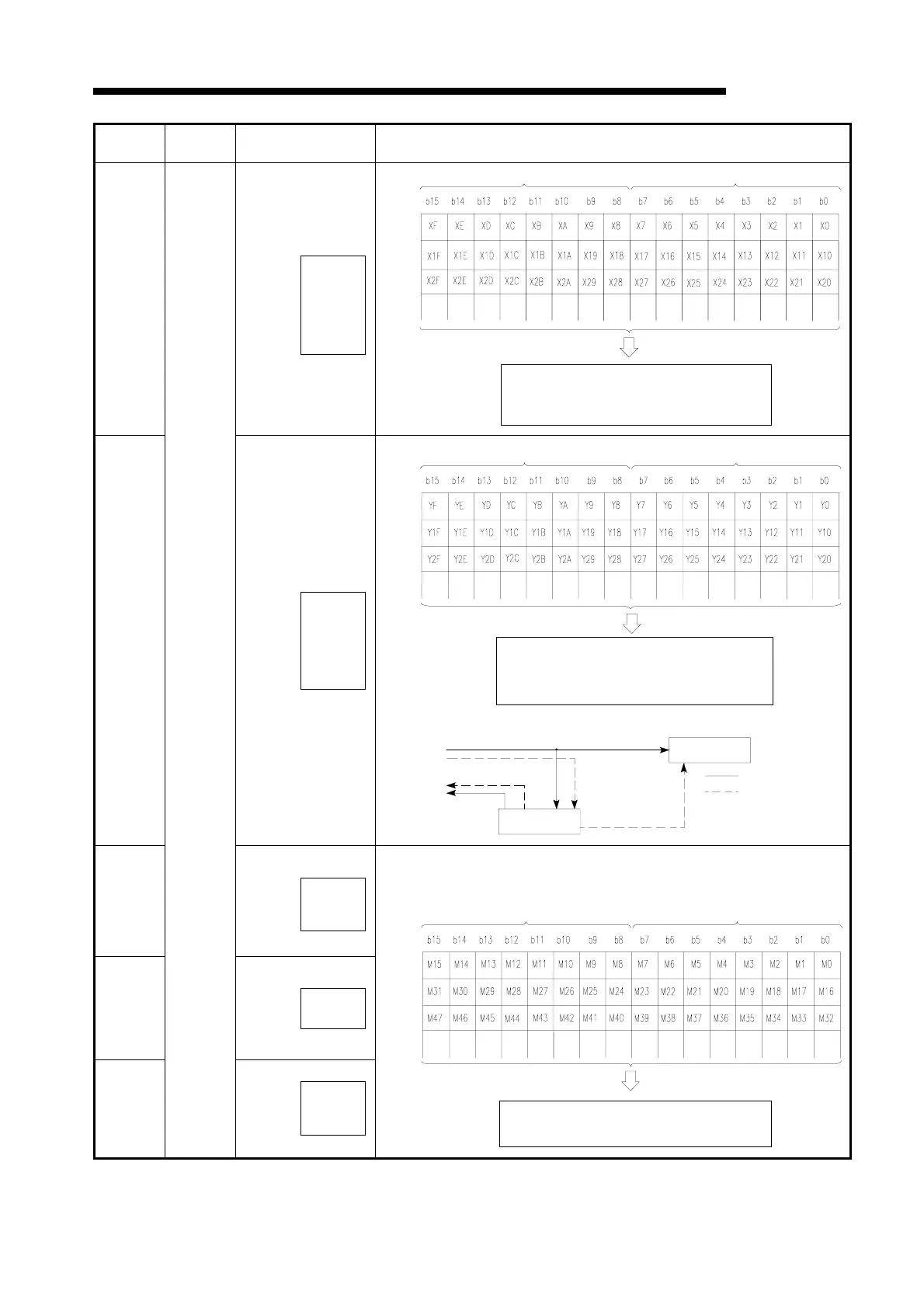
• Stores PC operation results and allows
read/write.
• Stores device ON/OFF data in one bit locations.
• 0 indicates OFF and 1 ON.
Example: M0 to 47 are as follows:
8200
H
8202
H
8204
H
Odd area Even area
8000H
8002
H
8004
H
• Stores ON/OFF data from an input unit,
read only.
• 0 indicates OFF and 1 ON.
Odd address
Even address
8200H
8202
H
8204
H
Odd address Even address
• Stores PC operation results and allows
read/write.
• 0 indicates OFF and 1 ON.
The output memory is accessed as below?
Write
Read
Direct mode
Refresh mode
Output module
Output memory
Output refresh after
END instruction is
executed

 Loading...


