(1)
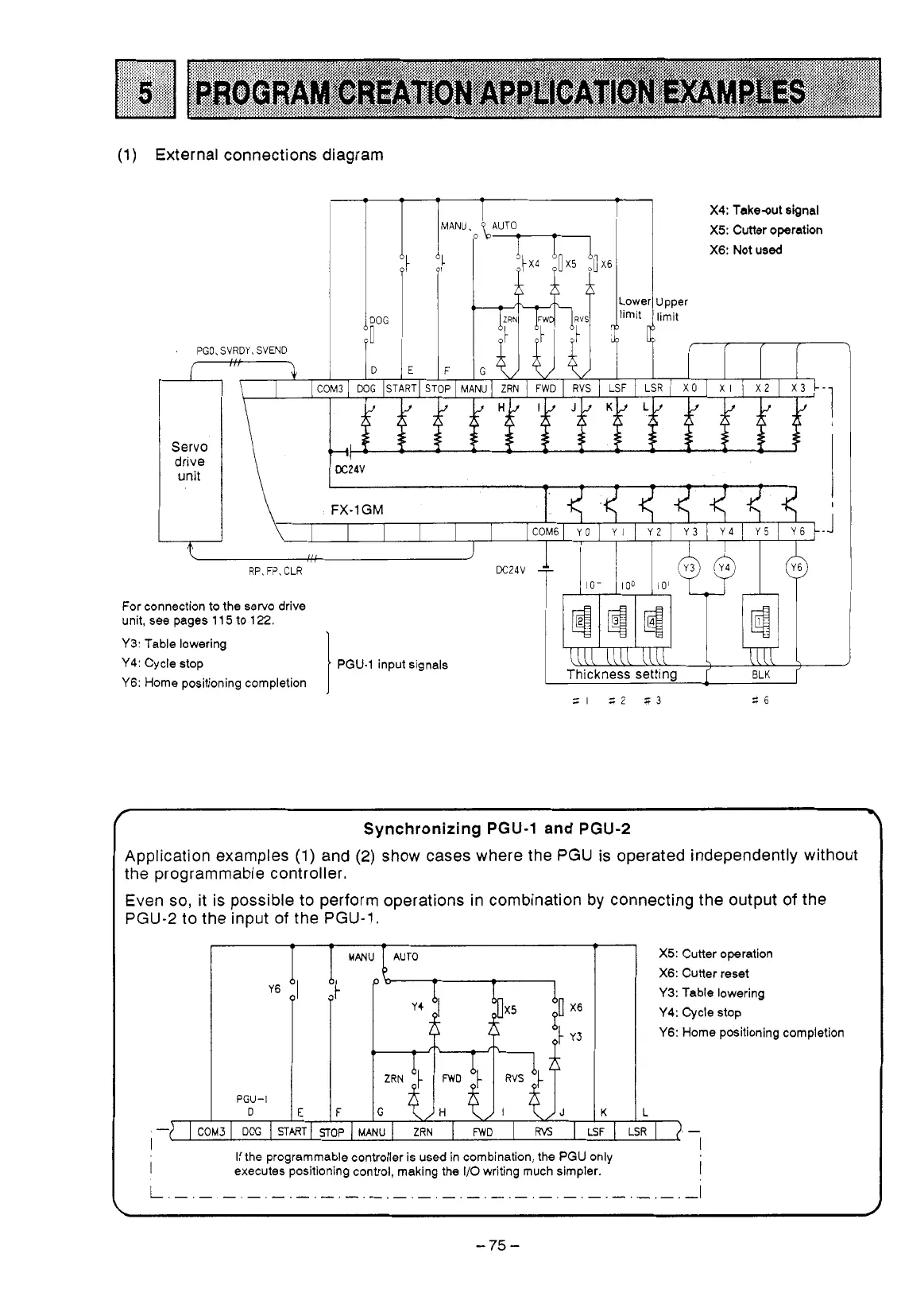
External connections diagram
PGO,
SVRDY,
WEND
-
AANU
F
$AUTO
iTI
X4:
Takeout signal
X5:
Cutter operation
X6:
Not used
Servo
drive
unit
.t
RP,
FP,
CLR
IO-
100
IO'
For connection
to
the servo drive
unit, see pages 11
5
to
122.
Y3: Table lowering
Y4:
Cycle stop PGU-1 input signals
uu
1111
iN
Y6: Home positioning completion
\
t
mw
a
Thickness
setting
-'
BLK
f
Synchronizing
PGU-1
and
PGU-2
Application examples
(1)
and
(2)
show
cases where the PGU is operated independently without
the programmable controller.
Even
so,
it is possible to perform operations in combination by connecting the output
of
the
PGU-2 to the input
of
the PGU-1,
I
I
-
If
the programmable controller is used in combination, the PGU only
executes positioning control, making
the
I/O writing much simpler.
I
X5:
Cutter operation
X6:
Cutter reset
Y3: Table lowering
Y4: Cycle
stop
Y6: Home positioning completion
L
I>.
-
I
__
-75-
 Loading...


