4
HARDWARE SPECIFICATIONS OF THE CPU MODULE
4.1 Performance Specifications
4.1.5 Universal model QCPU
4 - 17
1
OVERVIEW
2
SYSTEM
CONFIGURATION
3
GENERAL
SPECIFICATIONS
4
HARDWARE
SPECIFICATIONS OF
THE CPU MODULE
5
POWER SUPPLY
MODULE
6
BASE UNIT AND
EXTENSION CABLE
7
MEMORY CARD AND
BATTERY
8
CPU MODULE START-
UP PROCEDURES
*4 : The CPU module can execute up to 124 programs. The CPU module cannot execute 125 or more programs.
*5 : The one write operation may not be counted as one writing to a program memory.
The number of writing to the program memory can be checked by the special register (SD682 and SD683).
*6 : The one write operation may not be counted as one writing to the standard ROM.
The number of writing to the standard ROM can be checked by the special register (SD687 and SD688).
*7 : The number of points can be changed within the setting range. ( QCPU User's Manual (Function Explanation, Program
Fundamentals))
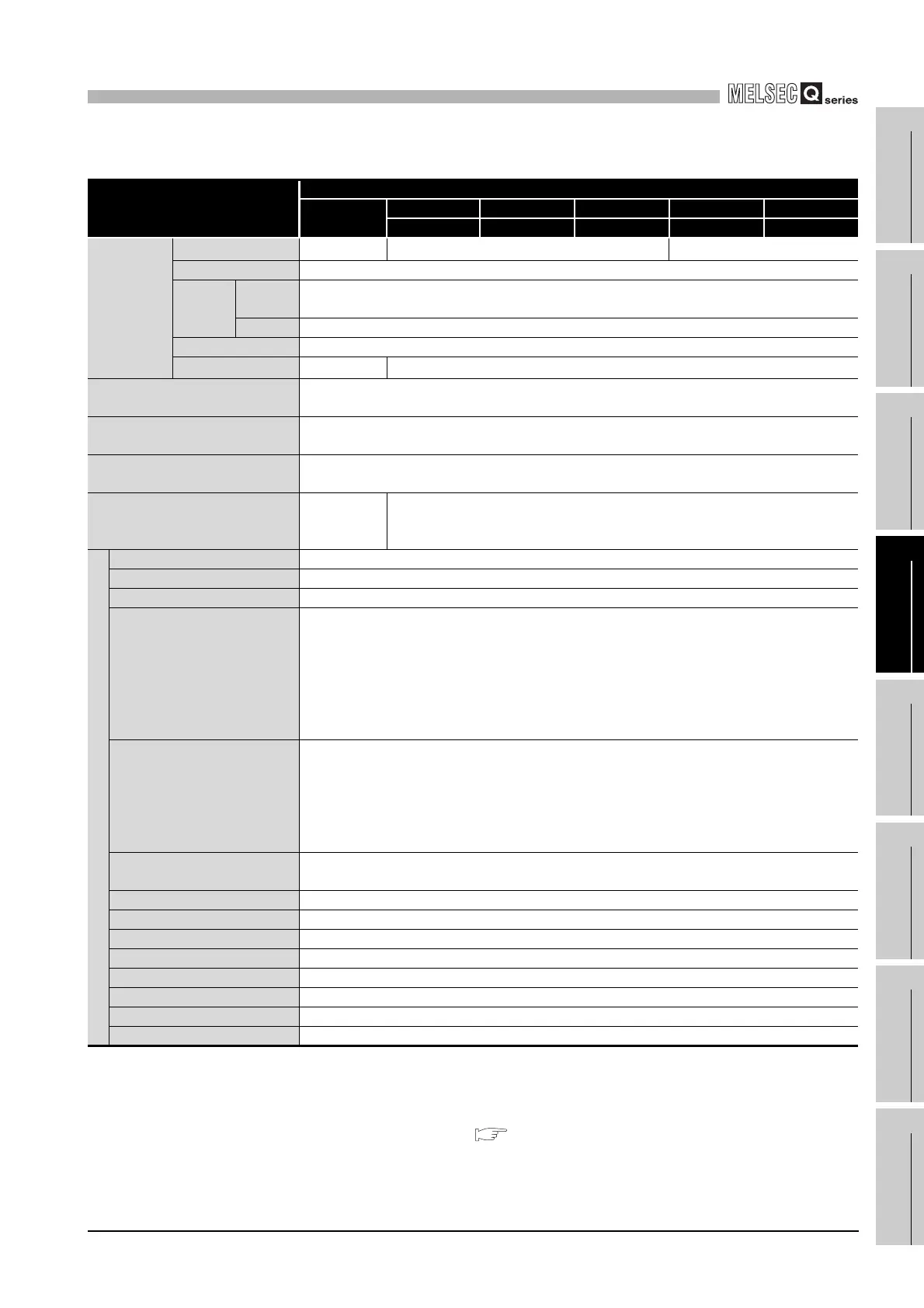
Table4.5 Performance Specifications
Item
Universal model QCPU
Q02UCPU
Q03UDCPU Q04UDHCPU Q06UDHCPU Q13UDHCPU Q26UDHCPU
Q03UDECPU Q04UDEHCPU Q06UDEHCPU Q13UDEHCPU Q26UDEHCPU
Max. number
of files stored
Program memory 64 124
252
*4
Memory card (RAM) 319(When the Q3MEM-8MBS is used)
Memory
card
(ROM)
Flash
card
288
ATA card 511
Standard RAM 3
Standard ROM 128
256
No. of times of writing data into the
program memory
Max. 100000 times
*4
No. of times of writing data into the
standard ROM
Max. 100000 times
*5
No. of I/O device points
(No. of points usable on program.)
8192 points (X/Y0 to 1FFF)
No. of I/O points
(No. of points accessible to the
actual I/O module.)
2048 points
(X/Y0 to 7FF)
4096 points (X/Y0 to FFF)
No. of device points
*7
Internal relay [M] 8192 points by default (M0-8191) (changeable)
Latch relay [L] 8192 points by default (L0-8191) (changeable)
Link relay [B] 8192 points by default (B0 to 1FFF) (changeable)
Timer [T]
2048 points by default (T0 to 2047) (changeable)
(Sharing of low- and high-speed timers)
The low- and high-speed timers are specified by the instructions.
The measurement unit of the low- and high-speed timers is set up by parameters.
(Low-speed timer: 1 to 1000ms, 1ms unit, 100ms by default)
(High-speed timer: 0.1 to 100.0ms, 0.1ms unit, 10.0ms by default)
Retentive timer [ST]
0 point by default (sharing of the low- and high-speed retentive timers) (changeable)
The low- and high-speed retentive timers are specified by the instructions.
The measurement unit of the low- and high-speed retentive timers is set up by parameters.
(Low-speed retentive timer: 1 to 1000ms, 1ms unit, 100ms by default)
(High-speed retentive timer: 0.1 to 100.0ms, 0.1ms unit, 10.0ms by default)
Counter [C]
• Normal counter, 1024 points by default
(C0 to 1023) (changeable)
Data register [D] 12288 points by default (D0 to 12287) (changeable)
Extended data register [D] 0 points by default (changeable)
Link register [W] 8192 points by default (W0 to 1FFF) (changeable)
Extended link register [W] 0 points by default (changeable)
Annunciator [F] 2048 points by default (F0 to 2047) (changeable)
Edge relay [V] 2048 points by default (V0 to 2047) (changeable)
Link special relay [SB] 2048 points by default (SB0 to 7FF) (changeable)
Link special register [SW] 2048 points by default (SW0 to 7FF) (changeable)
 Loading...