7 - 15
7.2 Battery (Q6BAT, Q7BAT, Q8BAT)
7.2.2 Installation of Battery
7
MEMORY CARD AND BATTERY
7.2.2 Installation of Battery
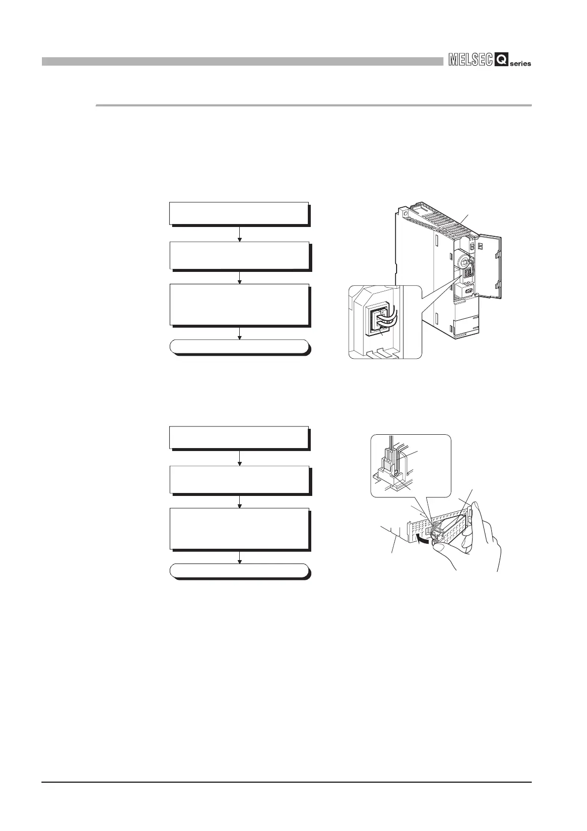
(1) Q6BAT battery installation procedure
The battery for the CPU module is shipped with its connector disconnected. Connect
the connector as follows.
Refer to Section 11.3 for the service life of the battery and how to replace the battery.
(a) Basic model QCPU
(b) High Performance model QCPU, Process CPU, Redundant CPU and
Universal model QCPU
Diagram 7.12 Q6BAT battery installation procedure
Diagram 7.13 Q6BAT battery installation procedure
CPU module
Connector
Completed
Insert the battery connector into the
connector pin on the case. Be sure that
the insertion direction is correct.
Open the CPU module front cover.
Confirm that the battery is loaded
correctly.
Completed
Insert the battery connector into the
connector pin on the case. Be sure that
the insertion direction is correct.
Open the CPU module bottom cover.
Confirm that the battery is loaded
correctly.
Battery
Connector
Connector
stopper
CPU module
 Loading...