12 - 18
12.2 Troubleshooting
12.2.13 Flowchart for when output module LED does not turn on
12
TROUBLESHOOTING
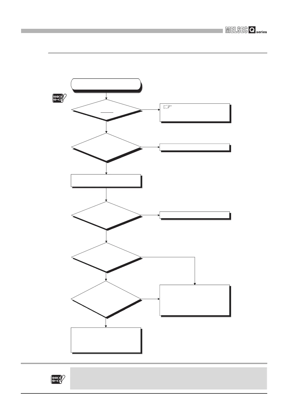
12.2.13 Flowchart for when output module LED does not turn on
The following shows the flowchart for when the output module LED does not turn on
during programmable controller operation.Note10
Diagram 12.10 Flowchart for when output module LED does not turn on
Note10
Basic
Note12.10
Reexamine the program.
Change the output number.
Is the "MODE"
LED on?
Does the output
number match?
Check the input/output number on
the GX Developer system monitor.
NO
NO
NO
NO
NO
(Flickering)
YES
YES
YES
YES
YES
Does the LED turn
on when another output
module is forcibly
turned on?
Does the
LED turn on when
the output module is changed for
another output module,
which is then forcibly
turned on?
CPU module, base unit, extension
cable hardware fault.
Please consult your local Mitsubishi
service center or representative,
explaining a detailed description of
the problem.
Output module hardware fault.
Please consult your local nearest
Mitsubishi or representative,
explaining a detailed description of
the problem.
Section 12.2.4 "Flowchart for
when the "MODE" LED is
flickering."
The output module LED
has not turned on
Is the LED on when the
output module is monitored
on GX Developer?
Section 12.2.4
Note12.10
The Basic model QCPU does not have the "MODE" LED. In the flowchart, proceed to "YES".
Basic
Note12.10
 Loading...