12
TROUBLESHOOTING
12.2 Troubleshooting
12.2.6 Flowchart for when the "POWER" LED turns on (red)
12 - 13
9
EMC AND LOW
VOLTAGE
DIRECTIVES
10
LOADING AND
INSTALLATION
11
MAINTENANCE AND
INSPECTION
12
TROUBLESHOOTING APPENDICES INDEX
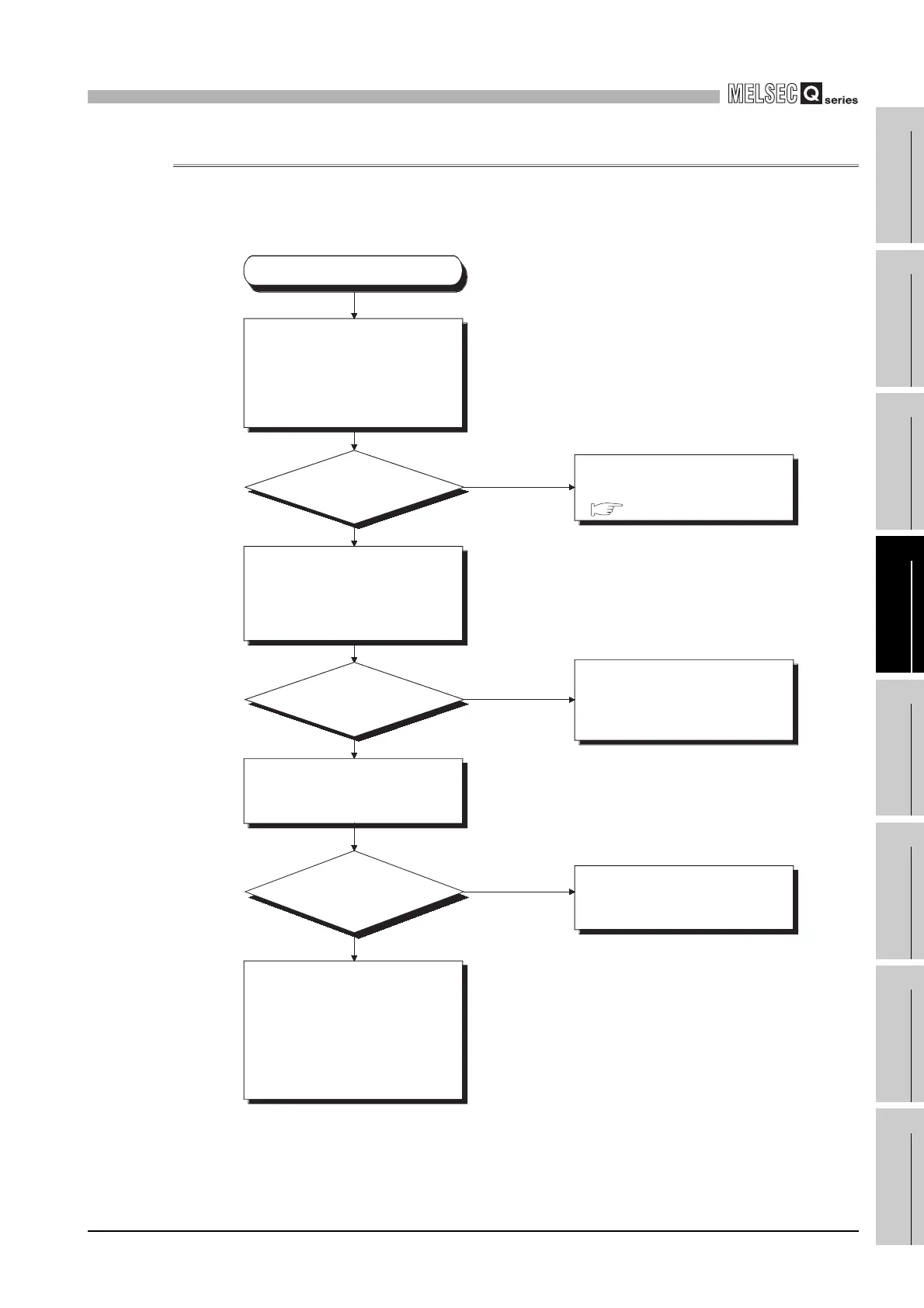
12.2.6 Flowchart for when the "POWER" LED turns on (red)
The following shows the flowchart for when the "POWER" LED of the redundant power
supply module turns on red at power-on or during operation of the programmable
controller.
Diagram 12.6 Flowchart for when the "POWER" LED is turned on red
How is the
"POWER" LED of the
redundant power supply
module?
The corresponding redundant power
supply module is faulty.
(Replace it with a normal one.)
( Section 12.4.2)
Remove the corresponding
redundant power supply module,
and mount it onto the normal
redundant base unit.
(At this time, do not mount any
modules other than the redundant
power supply module.)
Return the corresponding
redundant power supply module to
the original system, and remove all
modules other than the redundant
power supply module from the
redundant base unit.
Check the sum of internal current
consumptions of the modules that
comprise the system.
On (green)
Off or On (red)
On (green)
Off
The redundant base unit that
includes the corresponding
redundant power supply module is
faulty. (Replace it with a normal
redundant base unit.)
Does the total
current exceed the rated
output current of the power
supply module?
Reexamine the system configuration
to make the total current less than
the rated current consumption of one
redundant power supply module.
Hardware fault
check operations checks in the
order starting with the minimum
system.
If the module will not work, please
consalt your local nearest
Mitsubishi or representative,
explaining a detailed description of
the problem.
No
Yes
How is the
"POWER" LED of the
redundant power supply
module?
The "POWER" LED has
turned on (red).
Section 12.4.2
 Loading...