4
HARDWARE SPECIFICATIONS OF THE CPU MODULE
4.4 Universal Model QCPU
4.4.1 Part Names
4 - 41
1
OVERVIEW
2
SYSTEM
CONFIGURATION
3
GENERAL
SPECIFICATIONS
4
HARDWARE
SPECIFICATIONS OF
THE CPU MODULE
5
POWER SUPPLY
MODULE
6
BASE UNIT AND
EXTENSION CABLE
7
MEMORY CARD AND
BATTERY
8
CPU MODULE START-
UP PROCEDURES
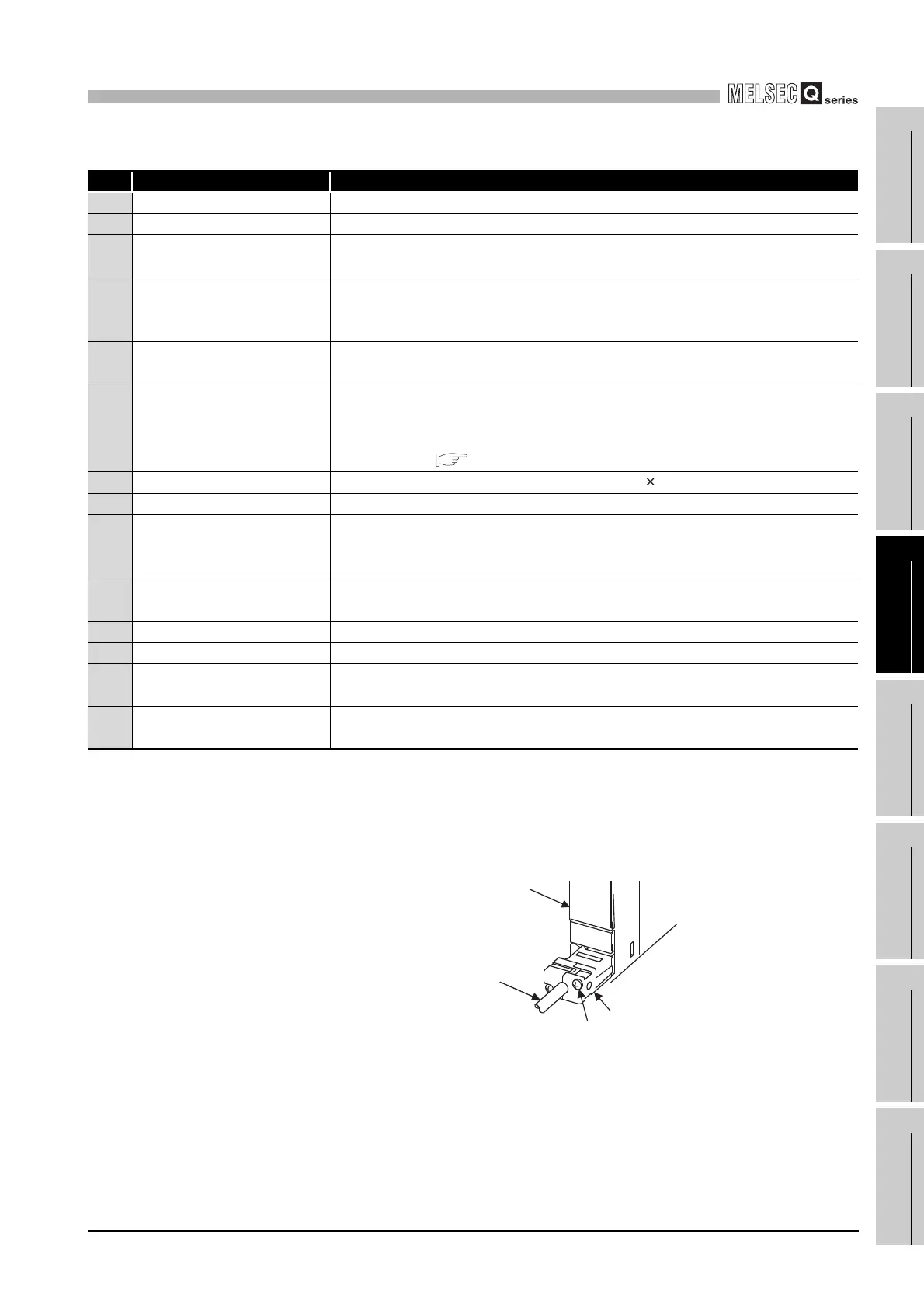
*1 : When a cable is to be connected to the RS-232 connector at all times, clamp the cable to prevent a loose connection,
shifting, or disconnection by pulling due to carelessness.
The Q6HLD-R2 type RS-232 Connector Disconnection Prevention Holder is available as a clamp for RS-232
connector.
*2 : Operate the RUN/STOP/RESET switch with your fingertips.
Do not use any tool such as a screwdriver because the switch part might be damaged.
Table4.9 Part Names
No. Name Application
8) Serial number display Displays the serial number described on the rating plate.
9) Memory card EJECT button Used to eject the memory card from the CPU module.
10)
Memory card loading
connector
Connector used to load the memory card to the CPU module.
11) USB connector
Connector for connection with USB-compatible peripheral device. (Connector type
miniB)
Can be connected by USB-dedicated cable.
12)
RS-232 connector
*1
Connector for connecting a peripheral device by RS-232.
Can be connected by RS-232 connection cable (QC30R2).
13)
RUN/STOP/RESET switch
*2
RUN : Executes sequence program operation.
STOP : Stops sequence program operation.
RESET : Performs hardware reset, operation error reset, operation initialization or
like. ( Section 4.4.3)
14) Module fixing screw hole
Hole for the screw used to fix to the base unit. (M3 12 screw)
15) Module fixing projection Projection used to fix the module to the base unit.
16) Battery connector pin
For connection of battery lead wires.
(When shipped from the factory, the lead wires are disconnected from the connector
to prevent the battery from consuming.)
17) Battery
Backup battery for use of standard RAM, timer function and power failure
compensation function.
18) Module mounting lever Lever used to mount the module to the base unit.
19) Ethernet connector Connector for connecting an Ethernet device (RJ-45 connector)
20) 100M LED
On: Connected at 100Mbps.
Off: Not connnected, or connected at 10Mbps
21) SD/RD LED
On: Data being sent/received
Off: No data being sent/received
Diagram 4.22 RS-232 cable fixing processing
Fixing screw
Q6HLD-R2
CPU module
RS-232 cable
 Loading...