5 - 22
5.2 Specifications
5.2.2 Selecting the power supply module
5
POWER SUPPLY MODULE
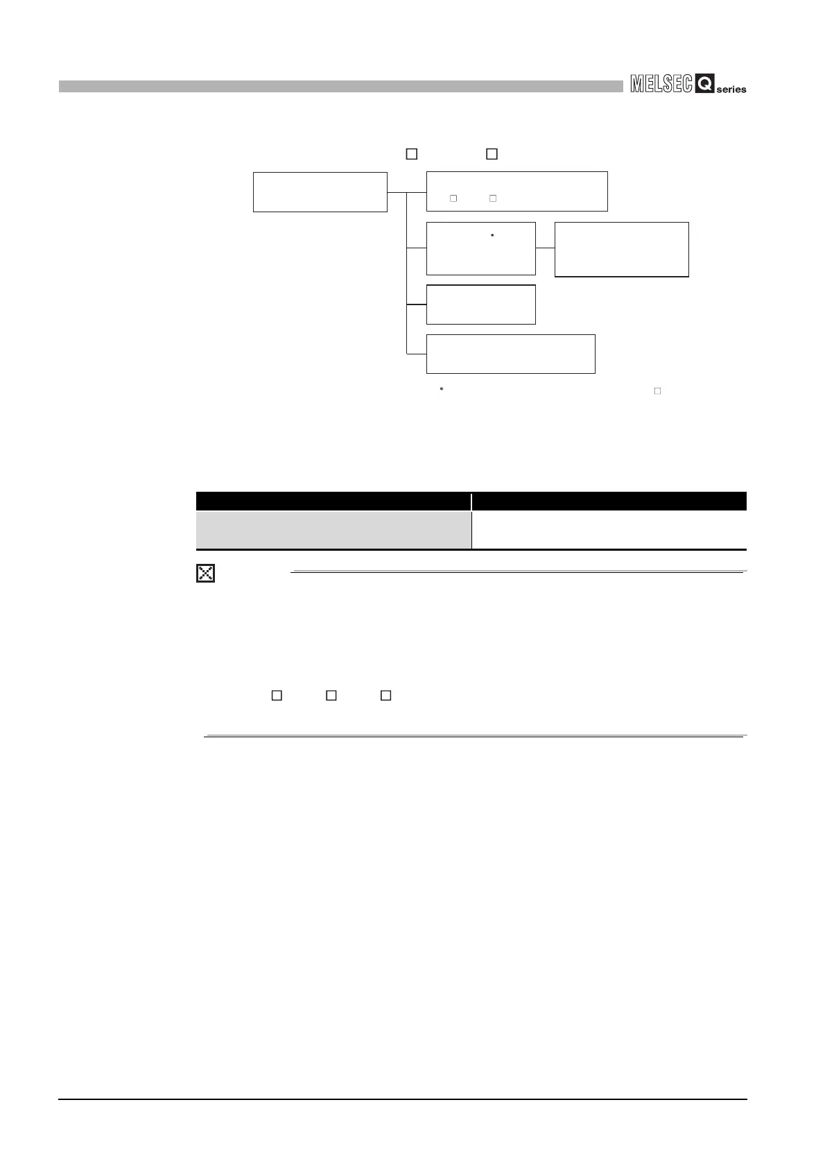
(3) When the base unit is Q3 RB or Q6 RB
POINT
When a redundant power supply system is configured and one redundant power
supply module has failed, the system is operated using the other redundant power
supply module only during replacement of the failed redundant power supply
module.
Therefore, keep the current consumption of the redundant power supply base unit
(Q3 RB/Q6 RB/Q6 WRB) within the 5VDC rated output current (8.5A) for one
redundant power supply module.
Diagram 5.3 Modules and peripheral device that are powered
by power supply module
Table5.16 5VD rated output current
5VDC rated output current Type
8.5A
Q63RP
Q64RP
Peripheral devices, converter,
cables, etc. (for connection
between CPU module and
PC)
Redundant power supply
module × 2 modules
I/O module QX10,
QY10, etc.
Intelligent function module Q64AD,
QJ71LP21-25, etc.
Redundant power supply base unit
Q3 RB, Q6 RB
CPU module 2
Q02(H)CPU,
Q06HCPU, etc.
2: Mounted on the redundant main base unit (Q3 RB)
 Loading...