6
BASE UNIT AND EXTENSION CABLE
6.1 Base Unit
6.1.2 Part Names
6 - 11
1
OVERVIEW
2
SYSTEM
CONFIGURATION
3
GENERAL
SPECIFICATIONS
4
HARDWARE
SPECIFICATIONS OF
THE CPU MODULE
5
POWER SUPPLY
MODULE
6
BASE UNIT AND
EXTENSION CABLE
7
MEMORY CARD AND
BATTERY
8
CPU MODULE START-
UP PROCEDURES
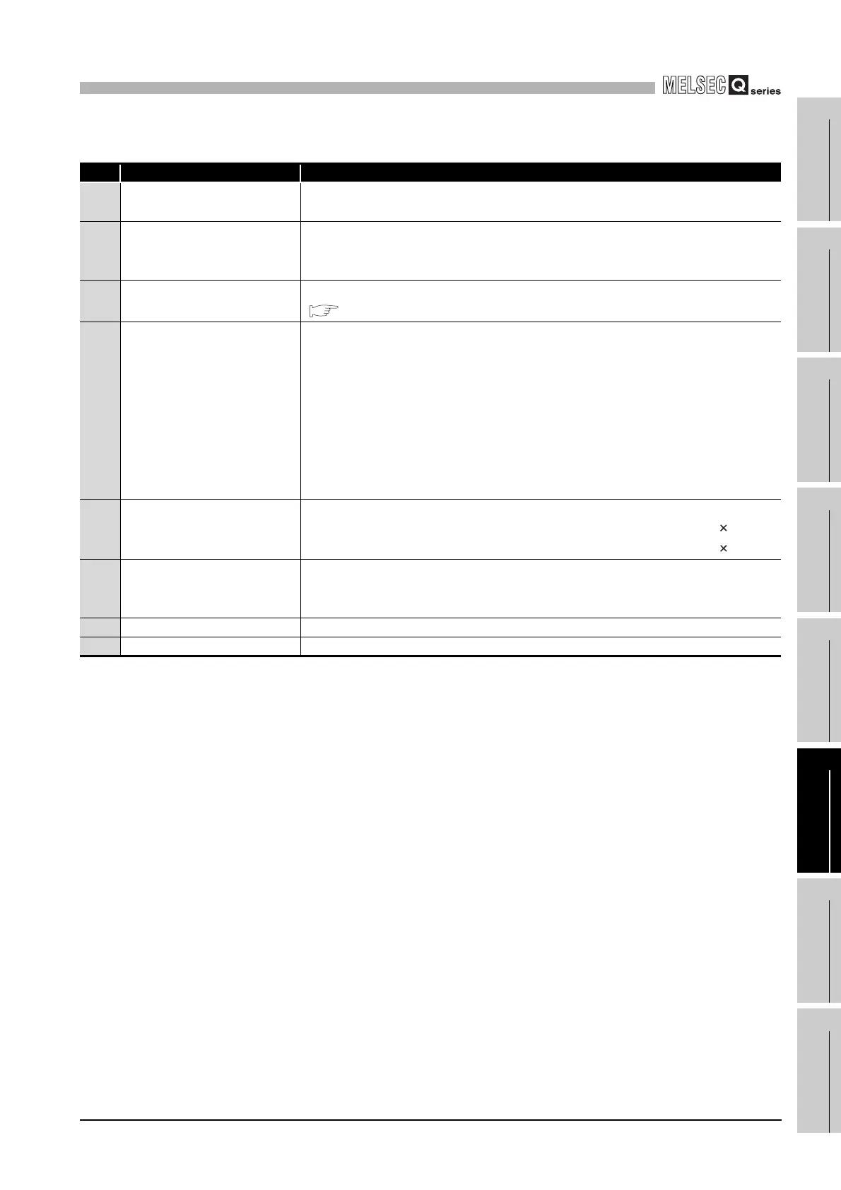
Table6.13 Part Names
No. Name Application
1) Extension cable connector
Connector for connecting an extension cable (for signal communications with the
main base unit or other extension base unit)
2) Base cover
Protective cover of extension cable connector.
Before connecting an extension cable, the part under OUT on the base cover must
be removed with a tool such as a flat blade screwdriver.
3) Stage No. setting connector
Connector for setting the number of stages of the extension base unit.
( Section 6.1.3)
4) Module connector
Connectors for installing the power supply module, I/O modules, and intelligent
function module/ special function module.
To those connectors located in the spare space where these modules are not
installed, apply the supplied connector cover or the blank cover module to prevent
entry of dirt.
Blank cover module applicable to Q52B, Q55B, Q63B,Q65B, Q68B and Q612B:
QG60
Blank cover module applicable to QA1S65B and QA1S68B: A1SG60
Blank cover module applicable to QA6BB and QA68B:AG60
5) Module fixing screw hole
Screw hole for fixing the module to the base unit.
Q52B, Q55B, Q63B,Q65B,Q68B and Q612B .....................Screw size: M3 12
QA1S6B, QA1S68B, QA65B and QA68B ...........................Screw size: M4 12
6) Base mounting hole
Hole for mounting this base unit on the panel of the control panel.
Q52B, Q55B, Q65B,Q68B and Q612B ...............................For M4 screw
QA1S6B, QA1S68B, QA65B and QA68B ...........................For M5 screw
7) DIN rail adapter mounting hole DIN rail adapter mounting hole.
8) Module fixing hole Cut out to accept projection and hook at rear of modules.
 Loading...