6
BASE UNIT AND EXTENSION CABLE
6.1 Base Unit
6.1.4 Guideline for Use of Extension Base Units
6 - 17
1
OVERVIEW
2
SYSTEM
CONFIGURATION
3
GENERAL
SPECIFICATIONS
4
HARDWARE
SPECIFICATIONS OF
THE CPU MODULE
5
POWER SUPPLY
MODULE
6
BASE UNIT AND
EXTENSION CABLE
7
MEMORY CARD AND
BATTERY
8
CPU MODULE START-
UP PROCEDURES
*1 : Sum total of current consumed by Q5 B and currents consumed by the I/O, intelligent function modules loaded on the
Q5 B.
The symbols including "I" (I1 to I7) vary with the modules loaded on the Q5 B. For details of the symbol, refer to the
user's manuals of the module used.
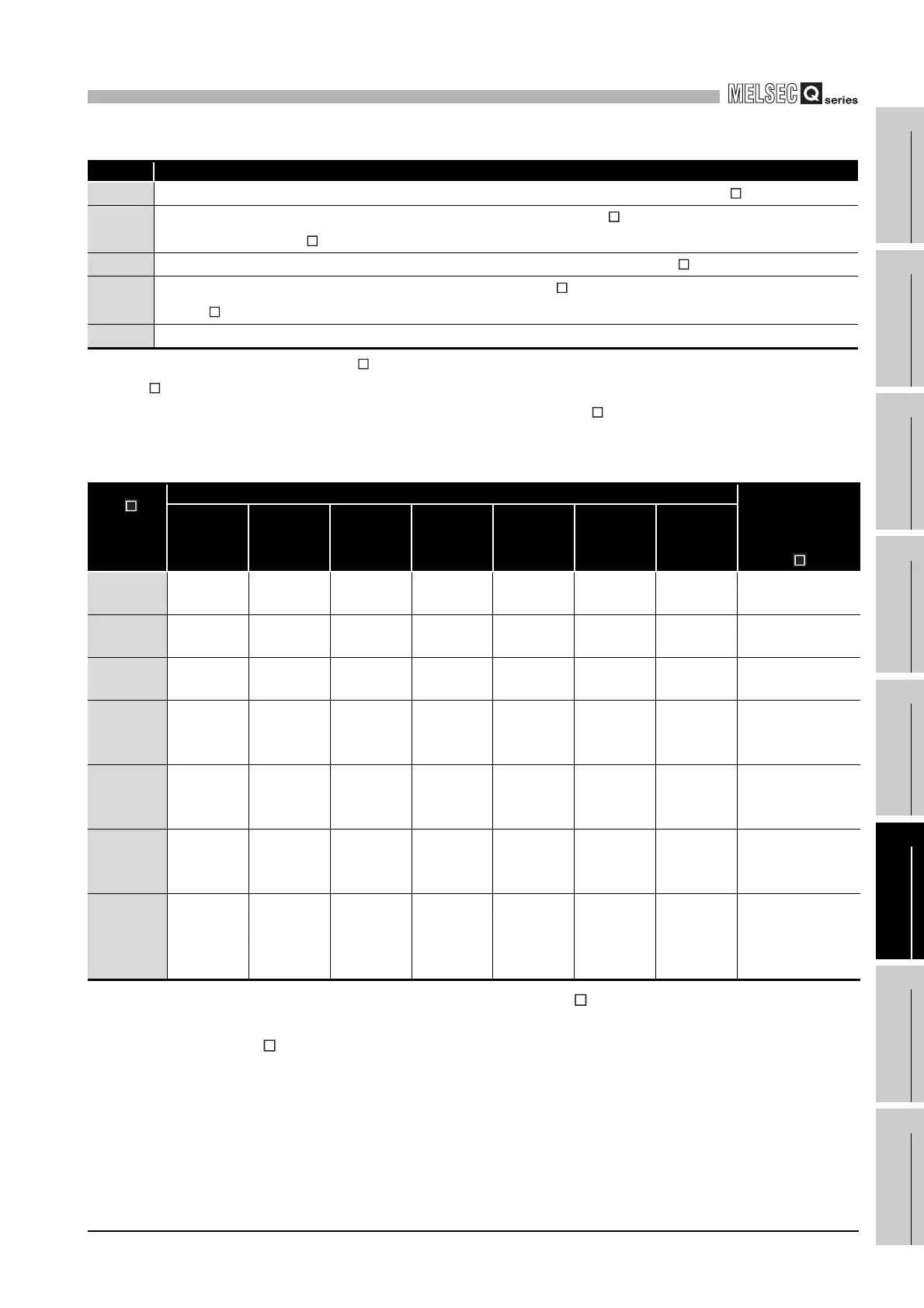
The voltage supplied to "IN" connector of the Q5 B in the final extension reaches 4.75
VDC or higher on the condition that the sum total of voltage drop to "IN" connector of
Q5 B (V) is 0.15V or lower.
Table6.18 Symbol explanation
Symbol Description
V1
Voltage drop at the extension cable between the main base unit and extension base unit (Q5 B)
Vn
Voltage drop at the extension cable between the extension base unit (Q5 B) (extension stage n-1) and
extension base unit (Q5 B) (extension stage n)
R1
Extension cable resistance between the main base unit and extension base unit (Q5 B)
Rn
Extension cable resistance between the extension base unit (Q5 B) (extension stage n-1) and extension base
unit (Q5 B) (extension stage n)
l1 to l7
5VDC current consumption among extension stage 1 to 7
*1
Table6.19 List for Calculating Voltage Drops Occurring at Extension Cables in System Consisting of Extensions 1 to 7
Q5 B
Loading
Position
Voltage Drop at Extension Cable on Corresponding Extension Unit Sum Total of
Voltage Drops to
"IN" Connector
of Q5 B (V)
V1 V2 V3 V4 V5 V6 V7
Extension
stage 1
R1•I1 ---- ---- ---- ---- ---- ---- V=V1
Extension
stage 2
R1 (I1+I2) R2•I2 ---- ---- ---- ---- ---- V= V1+V2
Extension
stage 3
R1
(I1+I2+I3)
R2 (I2+I3) R3•I3 ---- ---- ---- ---- V=V1+V2+V3
Extension
stage 4
R1
(I1+I2+I3+
I4)
R2
(I2+I3+I4)
R3 (I3+I4) R4•I4 ---- ---- ---- V=V1+V2+V3+V4
Extension
stage 5
R1
(I1+I2+I3+
I4+I5)
R2
(I2+I3+I4+
I5)
R3
(I3+I4+I5)
R4 (I4+I5) R5•I5 ---- ----
V=V1+V2+V3+V4
+V5
Extension
stage 6
R1
(I1+I2+I3+
I4+I5+I6)
R2
(I2+I3+I4+
I5+I6)
R3
(I3+I4+I5+
I6)
R4
(I4+I5+I6)
R5 (I5+I6) R6•I6 ----
V=V1+V2+V3+V4
+V5+V6
Extension
stage 7
R1
(I1+I2+I3+
I4+I5+I6+
I7)
R2
(I2+I3+I4+
I5+I6+I7)
R3
(I3+I4+I5+
I6+I7)
R4
(I4+I5+I6+
I7)
R5
(I5+I6+I7)
R6 (I6+I7) R7•I7
V=V1+V2+V3+V4
+V5+V6+V7
 Loading...