8
CPU MODULE START-UP PROCEDURES
8 - 2
1
OVERVIEW
2
SYSTEM
CONFIGURATION
3
GENERAL
SPECIFICATIONS
4
HARDWARE
SPECIFICATIONS OF
THE CPU MODULE
5
POWER SUPPLY
MODULE
6
BASE UNIT AND
EXTENSION CABLE
7
MEMORY CARD AND
BATTERY
8
CPU MODULE START-
UP PROCEDURES
*: The following types of diagnostics are available.
• PC diagnostics
• Network diagnostics
• Ethernet diagnostics
• CC-Link and CC-Link/LT diagnostics
POINT
For details of the wiring, connection and initial settings of intelligent function
modules, special function modules and network modules, refer to relevant
manuals.
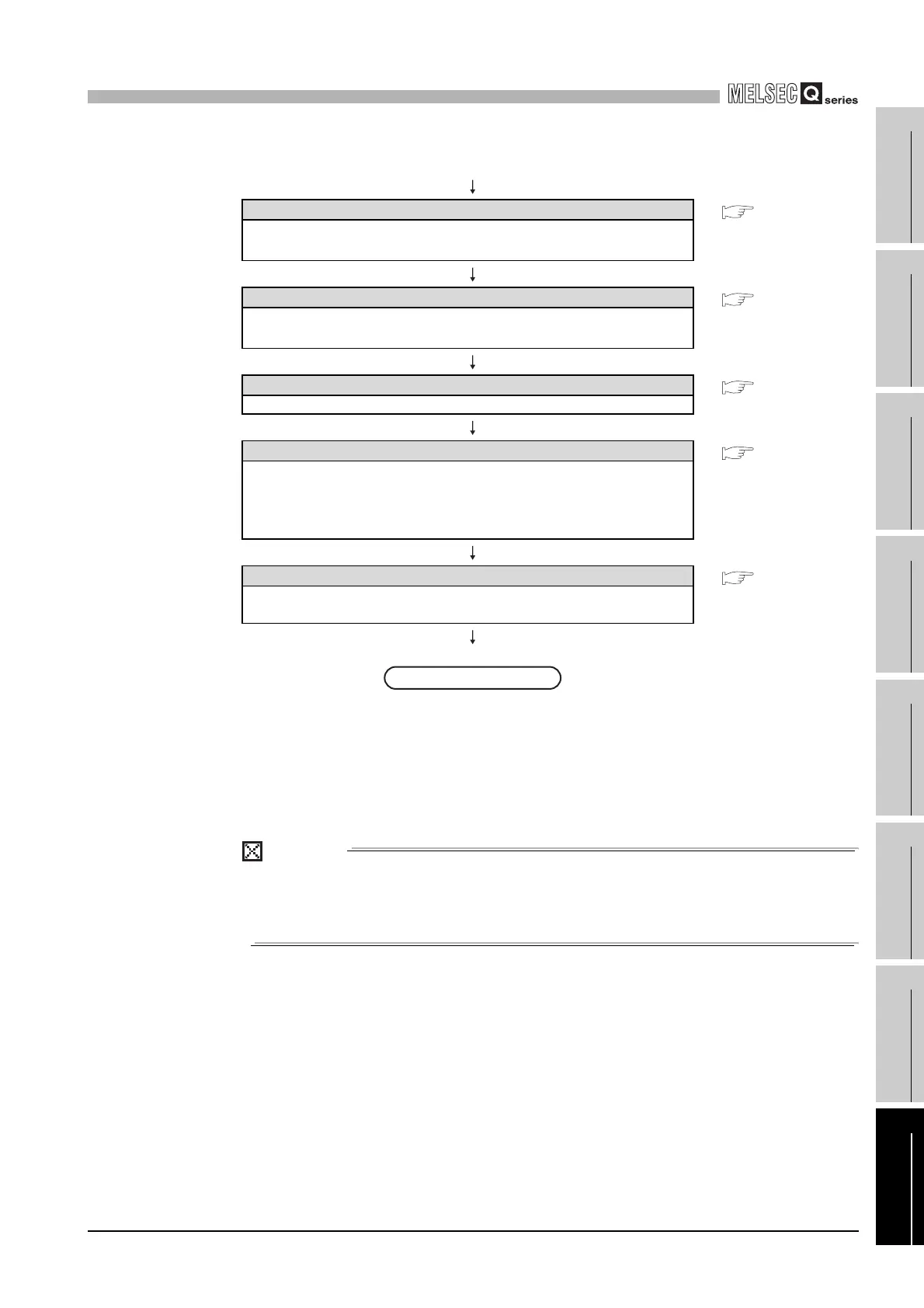
Memory formatting
• • • GX Developer
Operating
Manual
Format the memory to be used by the "PC Memory Formatting" of GX Developer.
Writing the parameters and programs
• • • GX Developer
Operating
Manual
Write the parameters and programs created by GX Developer into the CPU
module.
System reboot
• • • CHAPTER 4
Turn off and on the system power supply, or reset the CPU module.
Error check
• • • CHAPTER 4
Confirm that the ERR.LED of the CPU module is not lighting.
If the ERR.LED is lighting or blinking, identify the error cause by the system
monitor of GX Developer or diagnostics
*
to eliminate the error cause.
If the error is related to the parameters or programs, correct them.
Running of the CPU module
• • • CHAPTER 4
Run the CPU module, and then confirm that the RUN LED of the CPU module
lights up.
Diagram 8.2 CPU module start-up procedures (Continue)
(From previous page)
Completed
 Loading...