9
EMC AND LOW VOLTAGE DIRECTIVES
9.1 Requirements for Conformance to EMC Directive
9.1.3 Cables
9 - 7
9
EMC AND LOW
VOLTAGE
DIRECTIVES
10
LOADING AND
INSTALLATION
11
MAINTENANCE AND
INSPECTION
12
TROUBLESHOOTING APPENDICES INDEX
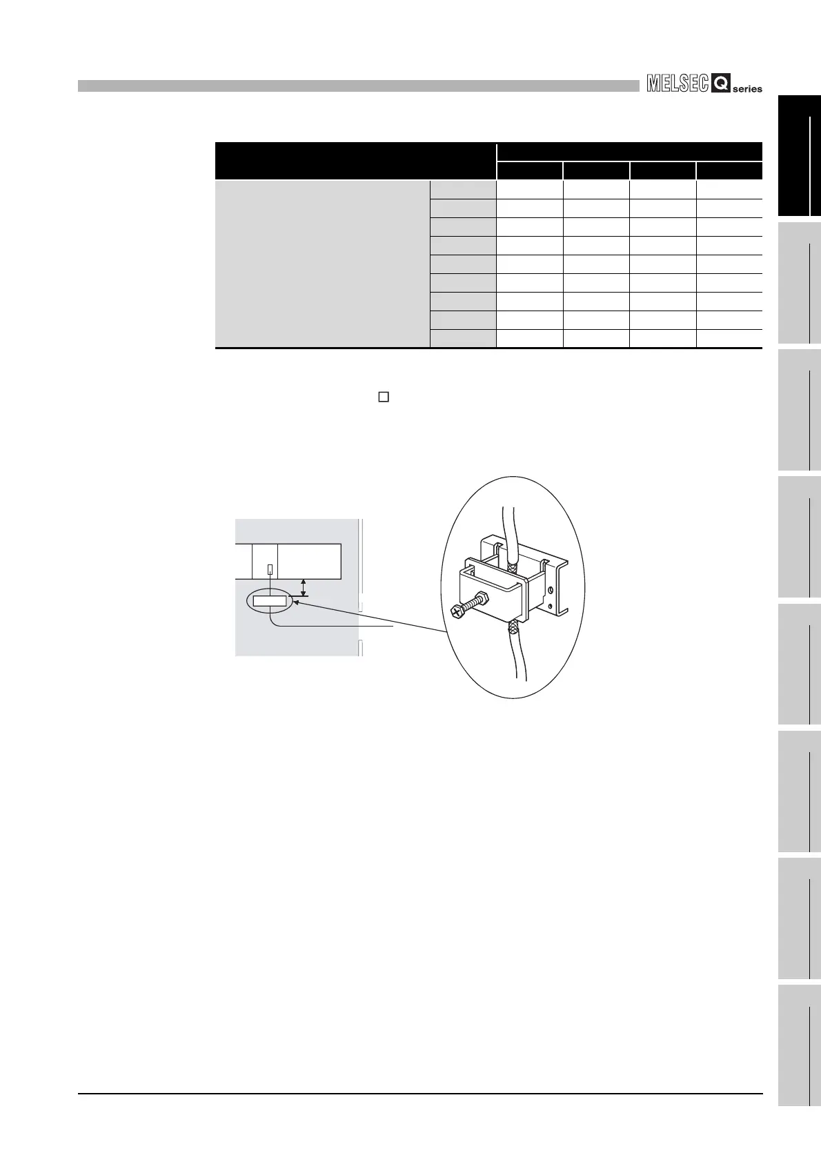
(6) Redundant CPU
Be sure to use the QC TR for the tracking cable, and ground the shielded part of the
cable to the panel with the AD75CK cable clamp (Mitsubishi Electric make).
(Ground the shield at a position 20 to 30cm (7.87 to 11.81 inch) away from the
module.)
(7) I/O signal lines and other communication cables
For the I/O signal lines (including common line) and other communication cables (RS-
232, RS-422, CC-Link, etc.), always ground the shields of the shield cables as in (1) if
they are pulled out of the control panel.
(8) Extension cable
For an extension cable, always ground the shields of the shield cables as in (1) if they
are pulled out of the control panel.
(9) Power line for external power supply terminal
The power line connecting to the external power supply terminal of the analog module
should be 30m or less.
(10)Power line of CC-Link remote module
Power line connecting to the external power supply terminal (compliant with I/O power
port of CE standard) should be 30m or less. Power line connecting to module power
supply terminal (compliant with I/O power port of CE standard) should be 10m or less.
Table9.2 Required number of AD75CK
Required Number of AD75CKs
Number of Used Channels
1 2 3 4
Number of used CT channel
01122
11223
21223
32233
42233
52334
62334
73344
83344
Diagram 9.10 AD75CK cable clamp mounting position
Inside control panel
QnPRHCPU
20 to 30cm
AD75CK
(7.87 to 11.81 inch)
 Loading...