10
LOADING AND INSTALLATION
10.2 Calculating Heat Generation of Programmable Controller
10 - 9
9
EMC AND LOW
VOLTAGE
DIRECTIVES
10
LOADING AND
INSTALLATION
11
MAINTENANCE AND
INSPECTION
12
TROUBLESHOOTING APPENDICES INDEX
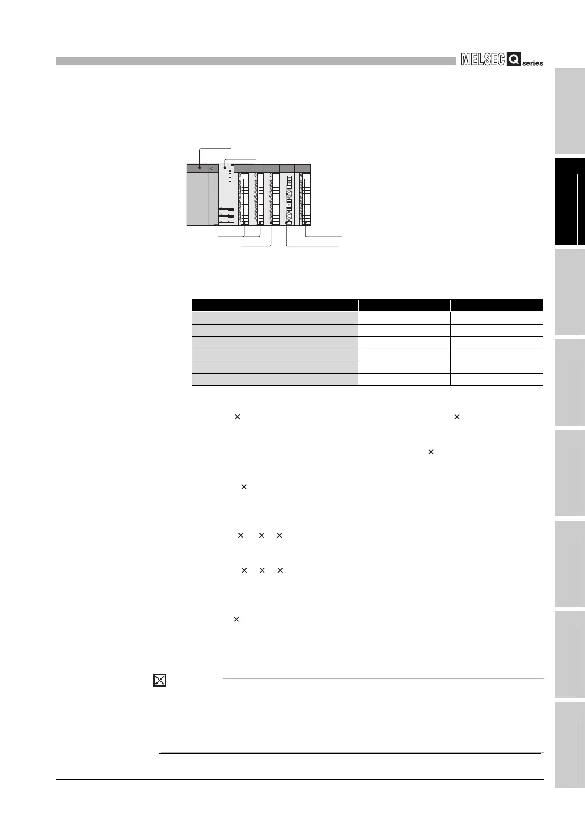
(7) Example of calculation of average power consumption
(a) System configuration
(b) 5VDC/24VDC current consumption of each module
Table10.2 5VDC/24VDC current consumption
(c) Power consumption of power supply module
W
PW = 3/7 (0.64 + 0.05 + 0.05 + 0.065 + 0.55 + 0.33 + 0.11) 5 = 3.85(W)
(d) Total power consumption for 5 VDC logic circuits of all module
W
5V = (0.64 + 0.05 + 0.05 + 0.065 + 0.55+ 0.33 + 0.11) 5 = 8.98(W)
(e) Total 24 VDC average power consumption of the output module
W
24V = 1.60 24 = 38.40(W)
(f) Average power consumption due to voltage drop in the output section of the
output module
W
OUT = 0.1 0.2 16 1 = 0.32(W)
(g) Average power consumption of the input section of the input module
W
IN = 0.00424321 = 3.07(W)
(h) Power consumption of the external power supply section of the intelligent
function module
W
S = 0.12 24=2.88(W)
(i) Power consumption of overall system
W = 3.85 + 8.98 + 38.40 + 0.32 + 3.07 + 2.88 = 57.50(W)
POINT
The value of the heat generated in a redundant system configuration (when the
Redundant CPU is used) is the sum of the two values for the control and standby
systems, each of which is calculated by the same method as that for the single
system.
Diagram 10.5 System configuration
module name 5VDC 24VDC
Q02HCPU 0.64A ----
QX40 0.05A ----
QY40P 0.065A 1.60A
QJ71LP-25 0.55A ----
Q62DA 0.33A 0.12A
Q35B 0.11A ----
QX40 Q62DA
QY40P
Q35B
QJ71LP21-25
Q02HCPU
Q61P-A1
 Loading...