10
LOADING AND INSTALLATION
10.6 Wiring
10.6.1 The precautions on the wiring
10 - 39
9
EMC AND LOW
VOLTAGE
DIRECTIVES
10
LOADING AND
INSTALLATION
11
MAINTENANCE AND
INSPECTION
12
TROUBLESHOOTING APPENDICES INDEX
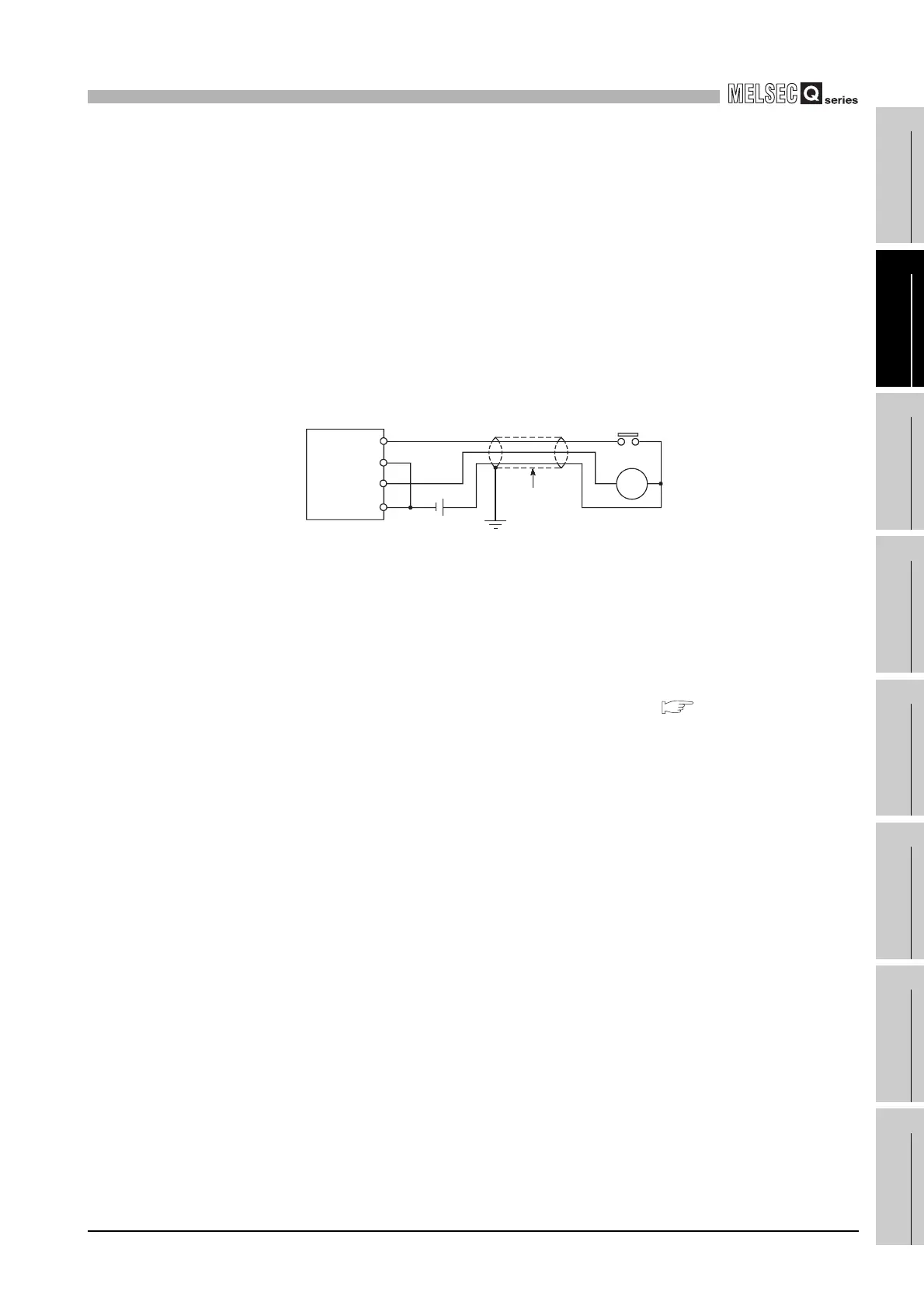
(2) Wiring of I/O equipment
• Insulation-sleeved crimping terminals cannot be used with the terminal block.
It is recommended to cover the wire connections of the crimping terminals with
mark or insulation tubes.
• The wires used for connection to the terminal block should be 0.3 to 0.75mm
2
in
core and 2.8mm (0.11 inch) max. in outside diameter.
• Run the input and output lines away from each other.
• When the wiring cannot be run away from the main circuit and power lines, use a
batch-shielded cable and ground it on the programmable controller side.
In some cases, ground it in the opposite side.
• Where wiring runs through piping, ground the piping without fail.
• Run the 24VDC input line away from the 100VAC and 200VAC lines.
• Wiring of 200m (686.67 ft.) or longer distance will give rise to leakage currents
due to the line capacity, resulting in a fault.
• To prevent an electric shock or operating module malfunction, provide the
external power supply of the module to be changed online with means that can
turn the power supply off individually, e.g. a switch. ( Section 12.4)
Refer to Section 12.5 for details.
• As a countermeasure against the power surge due to lightning, separate the AC
wiring and DC wiring and connect a surge absorber for lightning as shown in (1)
of item (10.6.1).
Failure to do so increases the risk of I/O device failure due to lightning.
Diagram 10.40 Wiring of I/O equipment
DC
RA
Programmable
controller
Shield cable
Input
Output
Shield jacket
 Loading...