10
LOADING AND INSTALLATION
10.6 Wiring
10.6.2 Connecting to the power supply module
10 - 43
9
EMC AND LOW
VOLTAGE
DIRECTIVES
10
LOADING AND
INSTALLATION
11
MAINTENANCE AND
INSPECTION
12
TROUBLESHOOTING APPENDICES INDEX
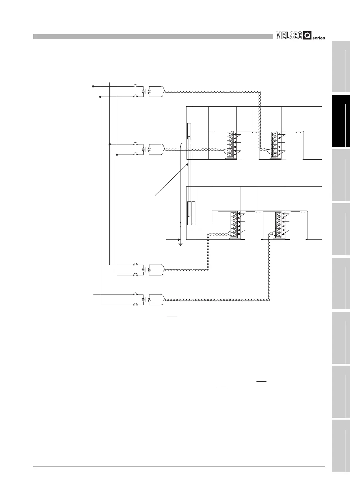
(2) Redundant power supply system
* 2: The operation of the ERR terminal is as fllows.
<When the redundant power supply module is mounted on the redundant power main base unit>
The terminal turns OFF (opens) when the AC power is not input, a CPU module stop error
(including a reset) occurs, the redundant power supply module fails, or the fuse of the redundant
power supply module is blown.
<When the redundant power supply module is mounted on the redundant power extension base
unit>
The terminal turns OFF (opens) when the redundant power supply module fails.
* 3 When input power is supplied to the redundant power supply module mounted on the redundant
power main base unit and the redundant power supply module mounted on the redundant power
extension base unit simultaneously, the ON (short) timing of the ERR
terminal on the redundant
power main base unit is later than that of the ERR
terminal on the redundant power extension
base unit by the initial processing time of the CPU module.
Diagram 10.43 Redundant power supply system wiring example
AC
100V/200VAC
AC
100V/200VAC
FG
LG
Q64RP
Ground wire
Extension cable
Grounding
CPU module
I/O module
Q64RP
FG
LG
INPUT
Q64RP
Redundant power main base unit
(Q38RB)
Redundant power extension base unit
(Q68RB)
FG
LG
100/
200VAC
INPUT
100/
200VAC
INPUT
100/
200VAC
INPUT
100/
200VAC
FG
LG
Q64RP
AC
100V/200VAC
AC
100V/200VAC
System BSystem A
ERR
2, 3
ERR
2, 3
ERR
2, 3
ERR
2, 3
 Loading...