11
MAINTENANCE AND INSPECTION
11.3 Battery Life and Replacement Procedure
11.3.5 SRAM card CPU module battery replacement procedure
11 - 31
9
EMC AND LOW
VOLTAGE
DIRECTIVES
10
LOADING AND
INSTALLATION
11
MAINTENANCE AND
INSPECTION
12
TROUBLESHOOTING APPENDICES INDEX
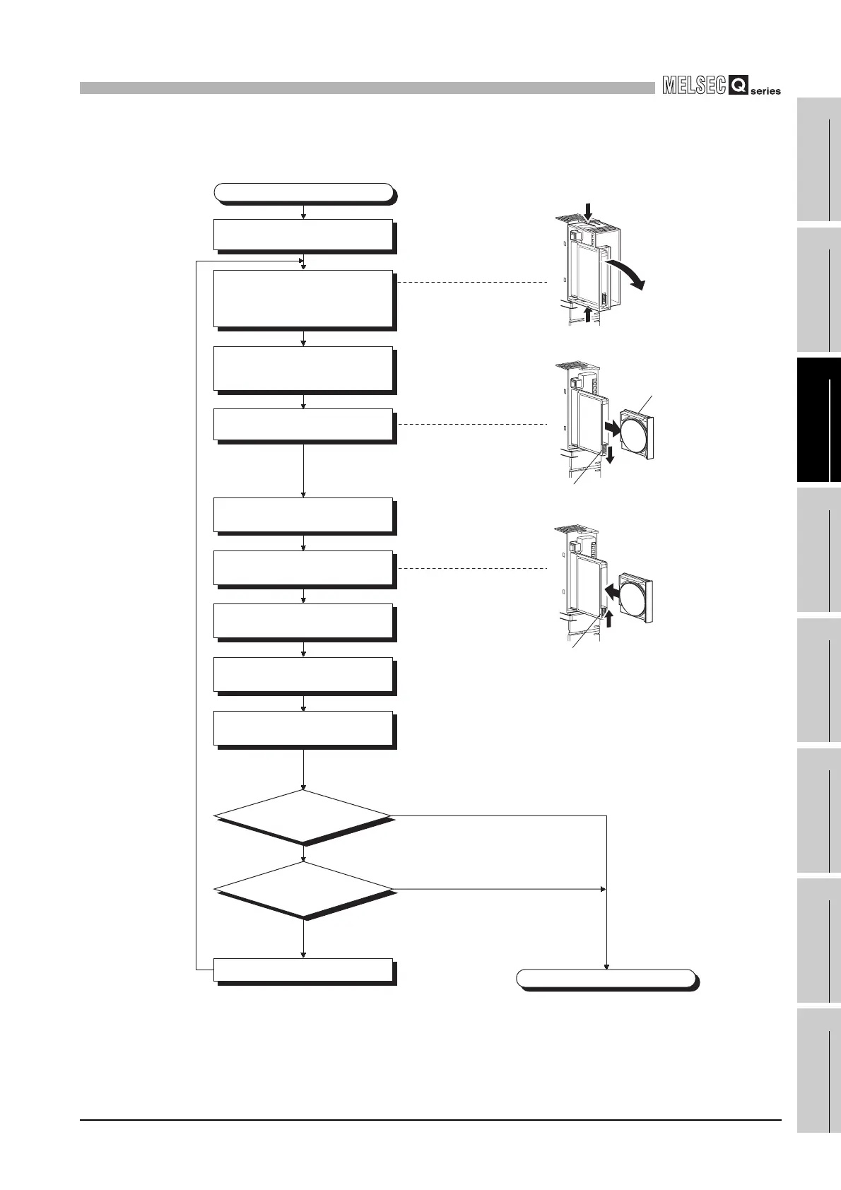
(2) Procedures for replacing battery of Q3MEM-4MBS or Q3MEM-8MBS
Diagram 11.8 SRAM card CPU module battery replacement procedure
Bit 1 and bit 2 are OFF.
Failure of SRAM card battery
OFF
ON
Bit 1 and bit 2 are ON.
Replacing battery
Completed
Backup the program and the
data.
Remove the battery holder from
the SRAM card.
Remove the old battery from its
holder.
Insert a new battery into the
holder in the correct direction.
Deeply insert the SRAM card
into the battery holder.
Set a battery holder fixing switch
to the LOCK position
Set the memory card protective
cover on the CPU module.
Remove a memory card
protective cover of the CPU
module at power-on status of
the programmable controller.
With a flat-blade screwdriver, etc.,
remove the battery holder locking
switch from the LOCK position.
Monitor
SD52 to check if bit 1 and bit
2 are ON.
Facing "+ (positive)"
up, install the battery
LOCK
CPU module
main unit
Battery holder
fixing switch
Monitor
SM52 to verify on/off.
Remove a caver,
pressing fixing claws
of top/bottom
CPU module
main unit
CPU module
main unit
Battery holde
Battery holder
fixing switch
Release
direction
 Loading...