12
TROUBLESHOOTING
12.5 I/O Module Troubleshooting
12.5.1 Input circuit troubleshooting
12 - 257
9
EMC AND LOW
VOLTAGE
DIRECTIVES
10
LOADING AND
INSTALLATION
11
MAINTENANCE AND
INSPECTION
12
TROUBLESHOOTING APPENDICES INDEX
<Calculation example of the resistance to be connected in Example 4>
• Connecting a switch with LED display, in which a maximum 2.33mA leakage
current flows when 24VDC is supplied to the QX40.
• In this case, the circuit does not satisfy the condition that the OFF current of the
QX40 is 1.7mA or less. Connect a resistance as follows.
(To next page)
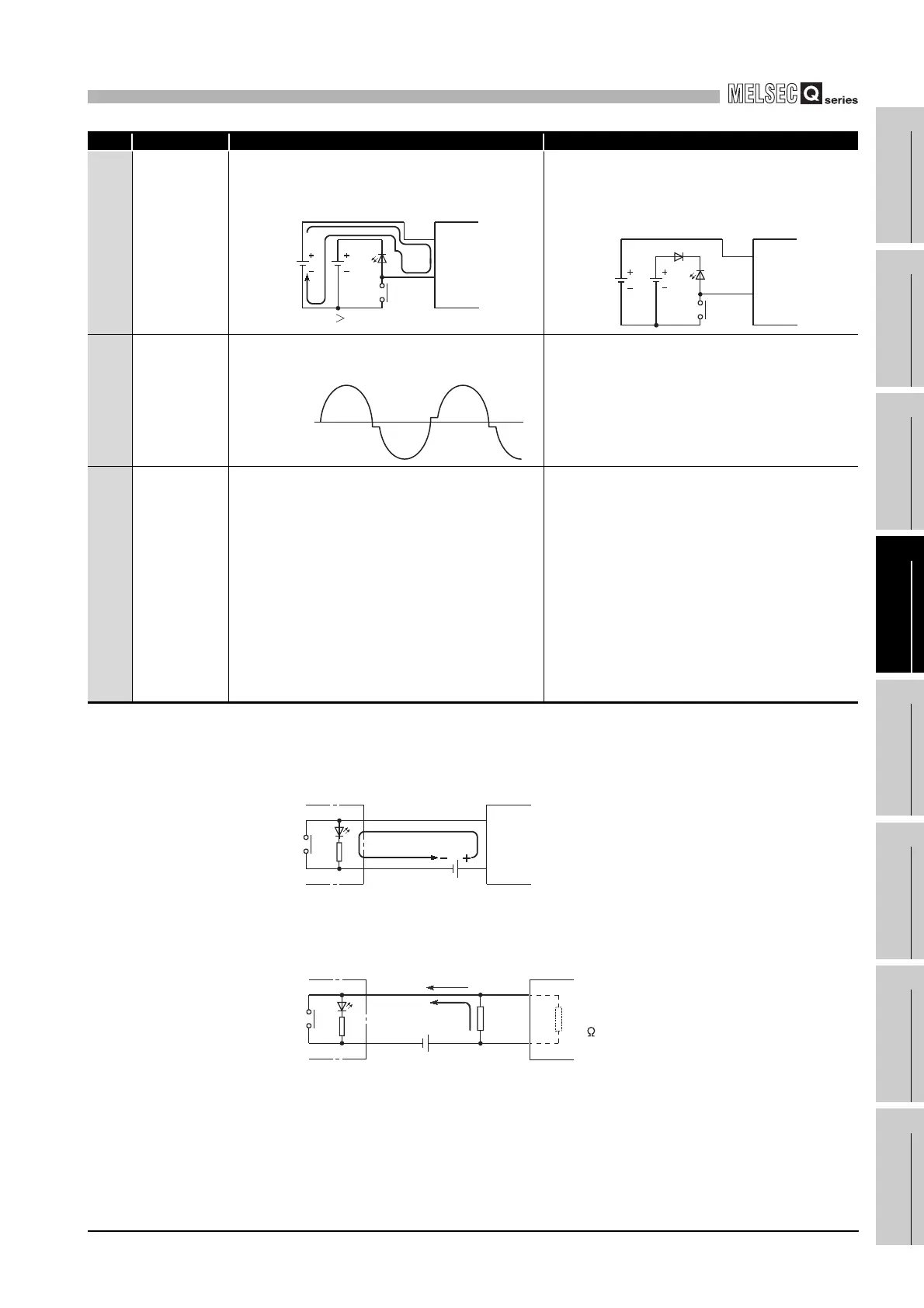
Condition Cause Corrective Action
Example 5
Input signal is
not turned
OFF.
• Sneak path due to the use of two power
supplies.
• Use only one power supply.
• Connect a sneak path prevention diode.
(Figure below)
Example 6
Input signal is
not turned ON
(AC input
module)
Stepwise distortion as shown below appears to
the zero cross voltage of input signal (AC).
Improve input signal waveform by using the on-
line system etc.
Example 7
False input
due to noise
Depending on response time setting, noise is
imported as input.
Change the response time setting.
Example: 1ms to 5ms
(When excessive noise is cyclic, shorter
response time setting may produce a higher
effect.) When the above action does not have an
effect, take measures against noise to block
excessive noise, e.g. avoid tying the power
cables and control cables in a bundle, and add
surge absorbers to the noise sources such as the
relays and contactors used with the same power
supply.
DC input
Input
module
E1
E2
E1 E2
DC input
Input
module
E1
E2
Zero cross
voltage
Input
module
Leakage current
24VDC
QX40
2.33mA
24VDC
QX40
2.33mA
I
Z=1.7mA
I
R=0.63mA
Input impedance
5.6k
R
 Loading...